Author Topic: Map Beam Current  (Read 3109 times)

Andrew Mott

  • Post Doc
  • ***
  • Posts: 11
Map Beam Current
« on: May 18, 2019, 11:13:32 AM »
Analyses being run: Quantitative Maps at 100nA

Issue: Weight Percent Totals Vary from the First Map Line (typically close to 100%) to the Last Map Line (anywhere from 95 - 98% depending on the map). The drop in weight total is consistent over time during mapping (as opposed to a single sudden drop).

Observation: In ProbeImage in the Conditions listed for the map, it always has Current (start) exactly the same as Current (end).

For example, I have a map that starts with a current of 100.86nA and when the run is complete I manually measure a current of 98.50. In the ProbeImage Conditions it has Current (start) and Current (end) as exactly 100.86 for both.

In CalcImage which current does it use to calculate the map - the current listed in the file settings (100nA), the current measured at the start of the map Current (start) (100.86nA), or is it intended to make a correction for beam drift between Current (start) and Current (end).

Thanks for your time.


John Donovan

  • Administrator
  • Emeritus
  • *****
  • Posts: 3270
  • Other duties as assigned...
    • Probe Software
Re: Map Beam Current
« Reply #1 on: May 18, 2019, 11:53:39 AM »
Hi Andrew,
Yes, we have implemented a beam drift correction in CalcImage based on the starting and ending beam currents imported from the .PrbImg x-ray maps as acquired in Probe Image.  As you mention, yes, it does assume a linear beam drift in CalcImage based on the pixel acquisition order. 

I'm pretty sure this beam drift correction for x-ray maps works on Cameca instruments (and JEOL beam scan maps) because they both acquire pixels from upper left to lower right (with the fast scan direction from left to right).

The JEOL stage map is however another animal, because it acquires pixels from upper right to lower left (with the fast scan direction from top to bottom).  We implemented code for both acquisition orders, but only the upper left to lower right pixel acquisition order code has been tested. We requested a JEOL test stage map where the beam current was deliberately forced to drift, from our beta testers, but no one has send us a set of test maps to check.  It probably works but always good to check!  ;D

You can see these start/end beam currents for each spectrometer pass in the CalcImage /CIP project file:


CalcImage also provides a standard intensity drift correction but only if you acquire standards before *and* after the x-ray map acquisition in Probe for EPMA, as described here:

https://probesoftware.com/smf/index.php?topic=41.msg3522#msg3522

Here is the beam current measurement section from an x-ray map I acquired in January this year on our SX100:

[Measured/BeamCurrent]
Start=2.61665e-08
End=2.61864e-08

Not sure why you are seeing the same exact beam current for both.  What version of Probe Image are you on?  The current version is 1.3.6.
« Last Edit: May 18, 2019, 12:00:26 PM by John Donovan »
John J. Donovan, Pres. 
(541) 343-3400

"Not Absolutely Certain, Yet Reliable"

Andrew Mott

  • Post Doc
  • ***
  • Posts: 11
Re: Map Beam Current
« Reply #2 on: May 20, 2019, 11:59:02 AM »
John,

The currents in the CIP project file match what I was manually measuring (as opposed to ProbeImage). If the current is beam drift corrected and I've standardize pre and post map, I guess I'll have to think about another reason why I might be losing weight percent as the map progresses (beam damage, etc.?). The only other weird thing from the maps is that while it collects from top left to bottom right, my weight percent maximum is in the top right corner and my minimum is in the bottom left. Thanks for the reply.

John Donovan

  • Administrator
  • Emeritus
  • *****
  • Posts: 3270
  • Other duties as assigned...
    • Probe Software
Re: Map Beam Current
« Reply #3 on: May 20, 2019, 01:25:18 PM »
Hi Andrew,
OK, that is good to know.

The currents in the CIP project file match what I was manually measuring (as opposed to ProbeImage).

I don't quite see how it could be possible that the beam current values in the .CIP file don't match the beam current values in the PrbImg files. Since that is where CalcImage gets them from when you create a new CalcImage project!

In any event, do you see a change in the standard intensities before/after?  Do you see a change in the standard intensities for more than one of the major element channels?  Is there enough drift in either the beam current or the standard intensities to explain what you observe?   

If you'd like you can send me the .CIP, .MDB and the PrbImg files in a zip file to my email and I can take a closer look at them.
john
« Last Edit: May 20, 2019, 05:11:59 PM by John Donovan »
John J. Donovan, Pres. 
(541) 343-3400

"Not Absolutely Certain, Yet Reliable"

Anette von der Handt

  • Global Moderator
  • Professor
  • *****
  • Posts: 351
    • UMN Probelab
Re: Map Beam Current
« Reply #4 on: May 21, 2019, 05:07:13 AM »
The first thing to come to mind would be that the sample is inclined and the focus was not set. If the map got progressively out of focus, you would lose intensity due to Bragg defocusing. So could that be the problem by any chance?
Against the dark, a tall white fountain played.

John Donovan

  • Administrator
  • Emeritus
  • *****
  • Posts: 3270
  • Other duties as assigned...
    • Probe Software
Re: Map Beam Current
« Reply #5 on: June 05, 2019, 08:25:57 PM »
OK. Andrew and I figured out what the problem was. Bottom line: the beam drift correction wasn't implemented correctly in CalcImage. This is now fixed and available for download from the Probe for EPMA Help | Update Probe for EPMA menu.

Now normally, with modern EPMA instruments equipped with beam current regulation, there is no significant drift in beam current (or WDS intensities for that matter- or what we refer to as standard intensity drift). So as long as one's electron gun is stable, and one's WDS spectrometers are stable, one will generally not require a drift correction for either beam current drift or WDS/standard intensity drift.

However, some instruments, usually near the end of filament life, will experience large changes in beam current. When acquiring x-ray maps for subsequent quantification, some beam current drifts will cause the detected x-ray intensities to change over long time scales.  One can only hope that such beam current drifts are linear over time, but of course one can only hope!

In any case, to correct for such beam current drifting, one must apply an interpolated beam current over the map acquisition, especially if the drift is over an extended period of time. Recently Andrew Mott (see original post above), reported that he was experiencing significant variation in his quantitative results over some 24 hour mapping runs. We now know that his filament was about to expire and hence the observed beam instability.

However, this provided us with an opportunity to check the beam drift (and standard drift) correction procedures in the quantification of x-ray maps. In this particular case we were seeing a drop in beam current of over 10%. Even worse, the change beam current over time was quite non-linear. Probably due to the old age of the filament. This brings us to how the beam current drift correction should work.

In Cameca instruments (and also JEOL instruments performing a beam scan acquisition), the pixel acquisition order is what one would expect.  The acquisition starts in the upper left, and proceeds to the lower right, with the X dimension being the direction of fast scanning. As depicted here:


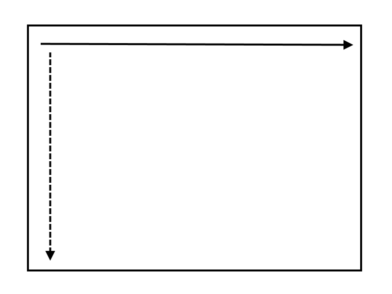
The solid line being the fast scan direction, and the dashed line being the slow scan direction.

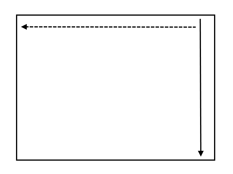
However, for JEOL instruments, while the beam scan pixel acquisition order is the same as the Cameca instruments, the stage scan acquisition pixel order is different. Specifically, the x-ray map acquisition proceeds from the upper right to the lower left with the fast scan direction in the Y dimension, and the slow scan direction being the X dimension direction as seen here:


My personal hypothesis is that this is a historical remnant from Nippon Steel requirements in the 1950s , but ultimately related to how Japanese newspapers written in Katakana are read.  I could be wrong.   In any case, the pixels are acquired in two different ways, and this is all complicated by the fact that the quantitative array processing in CalcImage is performed in yet another direction as seen here:


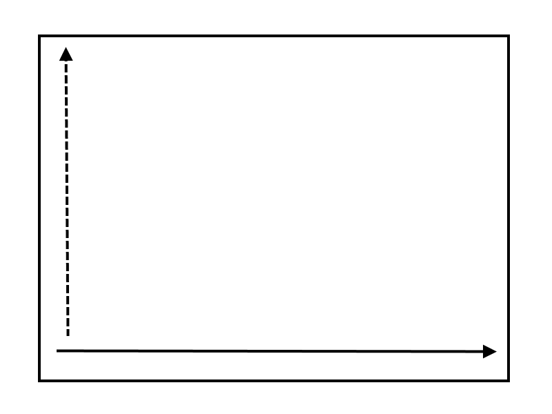
Hey, don't blame me, it's just math!

So in order to perform a proper time series drift correction for beam and/or standard intensity drift, one needs to calculate the fractional time based on the actual pixel acquisition order. But in two different manners, one for Cameca stage/beam scans and JEOL beam scans, and a different method for JEOL stage scans. Bottom line, we finally got this all working thanks to Andrew Mott and his failing filament!

More details to come, but if you have an unstable instrument you can test the improved beam drift and/or standard intensity drift correction in CalcImage, by simply updating from the Probe for EPMA Help | Update Probe for EPMA menu and trying the new drift corrections.
John J. Donovan, Pres. 
(541) 343-3400

"Not Absolutely Certain, Yet Reliable"

John Donovan

  • Administrator
  • Emeritus
  • *****
  • Posts: 3270
  • Other duties as assigned...
    • Probe Software
Re: Map Beam Current
« Reply #6 on: June 06, 2019, 10:11:30 AM »
Here is the test map that Andrew did on his SXFive over a 24 hour period. For this test he simply mapped his pure Fe metal standard.

Here is the raw on-peak intensity map:


As one can see all of the beam drift occurred in the first few hours of the scan, and was over a 10% change (100nA to 89 nA). After the map is quantified, the beam drift correction is CalcImage is automatically applied and attempts to correct for the beam drift as seen here:


Unfortunately because the beam drift was so non-linear, the linear beam drift correction could only do so much. Of course when one's beam is drifting this much one should not even attempt quantitative x-ray mapping!  But at the time we we weren't quite sure exactly what the problem was so we ran a test acquisition to find out.

Here's what the quant map looks performing a slice script output in CalcImage:


Darn, looks like I picked a starting point slightly outside the map so it starts at zero wt%!  Anyway, this is why we found the object naming issue in the slice, polygon and strip scripts yesterday, which is now fixed in the latest Probe for EPMA v. 12.6.3 update.

By the way, we would be very interested in obtaining a test example of a JEOL *stage* scan map showing significant beam drift. On the Cameca it turns out there is no way to force a change in the filament heat while the x-ray map is being acquired. You are locked out, even the command interpreter won't affect the filament heat.  So one has to wait for an unstable filament to reveal itself!

I do not know if this is also the case for JEOL instruments, so if someone could simulate a roughly linear beam drift during a JEOL stage scan on a pure element, even just a 10 minute acquisition, that would be cool.  The idea being to manually change the filament heat by say, a nA every line scan or so, so after a 20 x 20 pixel map with say, a 1 sec pixel count time, one would have a simulated beam drift example in roughly 8 minutes.

Then we could quant it in CalcImage and check that the beam drift correction is properly handling the pixel acquisition order of the JEOL stage scan.   8)
« Last Edit: June 06, 2019, 11:16:41 AM by John Donovan »
John J. Donovan, Pres. 
(541) 343-3400

"Not Absolutely Certain, Yet Reliable"

Philipp Poeml

  • Professor
  • ****
  • Posts: 219
Re: Map Beam Current
« Reply #7 on: June 11, 2019, 06:39:04 AM »
Hi John,

PeakSight does allow for a beam current reading every N lines or every N minutes of a map. That is very useful for us when we do 24 hour maps and our beam is not always super stable. With PeakSight we would read the beam current every 10 or 20 lines or every 30 mins or so.

Any chance to implement that into ProbeImage?

Thanks
Philipp


John Donovan

  • Administrator
  • Emeritus
  • *****
  • Posts: 3270
  • Other duties as assigned...
    • Probe Software
Re: Map Beam Current
« Reply #8 on: June 11, 2019, 08:29:53 AM »
Hi Philipp,
Yes, I know.  It is a nice feature.  I can check, but my recollection is that we would need additional information from Cameca to implement this.

On modern instruments I've seen, the beam drift is negligible. Beam regulation is very effective. And even if the beam drifts a little, as long as the beam drift is relatively linear, then the linear beam interpolation works great.  If the beam drift is non-linear, then one should probably get that fixed before attempting quantitative work.

On the example from Andrew Mott's SXFive, the filament was apparently near the end of it's life.
john
John J. Donovan, Pres. 
(541) 343-3400

"Not Absolutely Certain, Yet Reliable"

Philipp Poeml

  • Professor
  • ****
  • Posts: 219
Re: Map Beam Current
« Reply #9 on: June 13, 2019, 01:25:48 AM »
Hi John,

I understand what you are saying. Unfortunately for some reasons my lab is not so ideal as it should be. That's why this feature from PeakSight is really useful for me.

Maybe we could ask Cameca at QMA for some info?

Cheers
Philipp

John Donovan

  • Administrator
  • Emeritus
  • *****
  • Posts: 3270
  • Other duties as assigned...
    • Probe Software
Re: Map Beam Current
« Reply #10 on: June 13, 2019, 08:08:23 AM »
Hi John,

I understand what you are saying. Unfortunately for some reasons my lab is not so ideal as it should be. That's why this feature from PeakSight is really useful for me.

Maybe we could ask Cameca at QMA for some info?

Cheers
Philipp

We can ask!

Maybe you should bring this question up at their user meeting!    :)
John J. Donovan, Pres. 
(541) 343-3400

"Not Absolutely Certain, Yet Reliable"