Author Topic: plotting PAP phi-rho-z  (Read 9885 times)

Ben Buse

  • Professor
  • ****
  • Posts: 488
plotting PAP phi-rho-z
« on: April 26, 2018, 03:15:19 AM »
Hi,

This might be an off-the-wall idea, but would it be possible to extract the phi-rho-z curves and plot them from the calculations in calc-zaf. I think it might offer an alternative to monte-carlo when considering interaction volume (ok its only z, and you'd have to factor in density), it might also be useful for teaching matrix corrections? It would also allow direct comparison with phi-rho-z curves produced from monte carlo simulations aiding R&D.

Ben
« Last Edit: April 26, 2018, 03:55:39 AM by Ben Buse »

John Donovan

  • Administrator
  • Emeritus
  • *****
  • Posts: 3277
  • Other duties as assigned...
    • Probe Software
Re: plotting PAP phi-rho-z
« Reply #1 on: April 26, 2018, 09:03:22 AM »
Hi,

This might be an off-the-wall idea, but would it be possible to extract the phi-rho-z curves and plot them from the calculations in calc-zaf. I think it might offer an alternative to monte-carlo when considering interaction volume (ok its only z, and you'd have to factor in density), it might also be useful for teaching matrix corrections? It would also allow direct comparison with phi-rho-z curves produced from monte carlo simulations aiding R&D.

Ben

Hi Ben,
Actually I think it's a very interesting idea and it very much relates to the topic here that Mike and I were discussing just recently:

http://probesoftware.com/smf/index.php?topic=1065.0

Perhaps when you have a few minutes we can skype and discuss what might be possible?
john
John J. Donovan, Pres. 
(541) 343-3400

"Not Absolutely Certain, Yet Reliable"

Ben Buse

  • Professor
  • ****
  • Posts: 488
Re: plotting PAP phi-rho-z
« Reply #2 on: April 30, 2018, 05:26:22 AM »
Hi John,

That's interesting, this could be your answer!

As I see it it could either be a separate menu like x-ray range - where you ask for (1) material [composition as string]. (2) voltage, (3) density optional for distance, (4) element. Or what might be better is when you "calculate" in calczaf, there is an option to display phi-rho-curve for current sample for all elements or select element

The output could be a graph and a text file containing raw data.

Graph is no density supplied [graphs below are calculated using Armstrong 1990] Orange line after x-ray absorption


Graph if density supplied.


You could also if you like return depth at X% percentile

Ben
« Last Edit: April 13, 2020, 10:42:40 PM by John Donovan »

Ben Buse

  • Professor
  • ****
  • Posts: 488
Re: plotting PAP phi-rho-z
« Reply #3 on: April 30, 2018, 05:42:40 AM »
And just for fun here's a comparison to casino

« Last Edit: April 13, 2020, 10:38:11 PM by John Donovan »

John Donovan

  • Administrator
  • Emeritus
  • *****
  • Posts: 3277
  • Other duties as assigned...
    • Probe Software
Re: plotting PAP phi-rho-z
« Reply #4 on: May 09, 2018, 01:59:58 PM »
This might be an off-the-wall idea, but would it be possible to extract the phi-rho-z curves and plot them from the calculations in calc-zaf. I think it might offer an alternative to monte-carlo when considering interaction volume (ok its only z, and you'd have to factor in density), it might also be useful for teaching matrix corrections? It would also allow direct comparison with phi-rho-z curves produced from monte carlo simulations aiding R&D.

Hi Ben,
Easier said than done, but with a lot of help from Paul Carpenter and Brian Joy we managed to implement something that hopefully will be useful.  Here's an example of Fe2SiO4 (D=3) at 15 keV:


Right now we only calculate these curves for the phi-rho-z methods *other* than PAP and XPP.  Brian Joy is working on the PAP and XPP curves and as soon as he finishes, we will implement that next.  Basically one simply checks the Plot Phi-Rho-Z Curves checkbox here and then runs a calculation in CalcZAF to obtain the plot output:


But you can also plot microns depth if you have properly specified the density from the Calculation Options dialog:


Note that the generated intensity curve is a thick line and the emitted intensity is a thin line. Finally here is a more complicated sample (NIST K-411 glass):


This feature is now available in CalcZAF v. 12.3.2 by updating CalcZAF from the Help menu.
« Last Edit: April 13, 2020, 10:18:02 PM by John Donovan »
John J. Donovan, Pres. 
(541) 343-3400

"Not Absolutely Certain, Yet Reliable"

John Donovan

  • Administrator
  • Emeritus
  • *****
  • Posts: 3277
  • Other duties as assigned...
    • Probe Software
Re: plotting PAP phi-rho-z
« Reply #5 on: May 10, 2018, 10:49:09 PM »
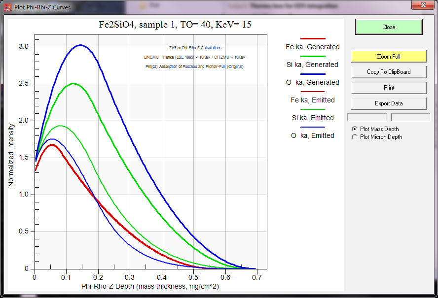
With Brian Joy's help we implemented prz plots for the PAP and XPP methods in CalcZAF v. 12.3.3.  Here is a plot of the PAP curves for Fe2SiO4:


And here is the XPP plot:


As many of you know, the PAP prz method is interesting because it attempts to be physically accurate with regard to depth as opposed to other analytical models that focused primarily on the area under the curve (the genesis of PAP was thin film modeling by Pouchou). However, the validity of area under the curve analytical models is demonstrated by the surprising accuracy of the Love/Scott quadrilateral "prz" method which assumes the x-ray production distribution curve with depth is a rectangle!  But since we're essentially comparing the ratio of the calculated intensity in a pure element with that of the compound, shape really doesn't matter.

Unless you really want to know the actual depth distribution of the x-ray production (e.g., a thin film).  This is basically what I was getting at in this recent topic here:

http://probesoftware.com/smf/index.php?topic=1065.0

Also, just as a reminder, the intensities plotted here are normalized intensities and only reflect the elements present, regardless of their concentrations.  The only effect concentration has on the plotted intensities are seen in the emitted intensity curves due to the average mass absorption coefficients.

To demonstrate, here is a PAP model of TiO2 at 15 keV:


Here we can see that although oxygen x-rays are generated at a considerable depth, the O Ka x-ray emission volume is mostly within the top 200 nm of the sample.  Download the latest CalcZAF 12.3.3 and try the same calculation but with the formula Ti99O or TiO99.
« Last Edit: April 13, 2020, 10:03:34 PM by John Donovan »
John J. Donovan, Pres. 
(541) 343-3400

"Not Absolutely Certain, Yet Reliable"

Brian Joy

  • Professor
  • ****
  • Posts: 296
Re: plotting PAP phi-rho-z
« Reply #6 on: May 11, 2018, 08:00:42 AM »
Also, just as a reminder, the intensities plotted here are normalized intensities and only reflect the elements present, regardless of their concentrations.  The only effect concentration has on the plotted intensities are seen in the emitted intensity curves due to the average mass absorption coefficients.

But keep in mind that the model parameters, for instance phi0, Rm, Rc, and Rx in the PAP model are functions of composition, so phi(rho*z), the integral of which (between limits rho*z = 0 and rho*z = Rx) gives generated intensity, does in fact vary with composition.
Brian Joy
Queen's University
Kingston, Ontario
JEOL JXA-8230

John Donovan

  • Administrator
  • Emeritus
  • *****
  • Posts: 3277
  • Other duties as assigned...
    • Probe Software
Re: plotting PAP phi-rho-z
« Reply #7 on: May 11, 2018, 08:34:28 AM »
Also, just as a reminder, the intensities plotted here are normalized intensities and only reflect the elements present, regardless of their concentrations.  The only effect concentration has on the plotted intensities are seen in the emitted intensity curves due to the average mass absorption coefficients.

But keep in mind that the model parameters, for instance phi0, Rm, Rc, and Rx in the PAP model are functions of composition, so phi(rho*z), the integral of which (between limits rho*z = 0 and rho*z = Rx) gives generated intensity, does in fact vary with composition.

But the generated curves are normalized to the intensity at the surface, yes?
John J. Donovan, Pres. 
(541) 343-3400

"Not Absolutely Certain, Yet Reliable"

Brian Joy

  • Professor
  • ****
  • Posts: 296
Re: plotting PAP phi-rho-z
« Reply #8 on: May 11, 2018, 08:58:26 AM »
Also, just as a reminder, the intensities plotted here are normalized intensities and only reflect the elements present, regardless of their concentrations.  The only effect concentration has on the plotted intensities are seen in the emitted intensity curves due to the average mass absorption coefficients.

But keep in mind that the model parameters, for instance phi0, Rm, Rc, and Rx in the PAP model are functions of composition, so phi(rho*z), the integral of which (between limits rho*z = 0 and rho*z = Rx) gives generated intensity, does in fact vary with composition.

But the generated curves are normalized to the intensity at the surface, yes?

No, the generated intensity is normalized to the intensity produced by a thin film (mass thickness = d(rho*z)) of the pure element in a vacuum.  See, for instance, Electron Probe Quantitation, bottom of p. 32.
Brian Joy
Queen's University
Kingston, Ontario
JEOL JXA-8230

John Donovan

  • Administrator
  • Emeritus
  • *****
  • Posts: 3277
  • Other duties as assigned...
    • Probe Software
Re: plotting PAP phi-rho-z
« Reply #9 on: May 11, 2018, 09:09:45 AM »
Also, just as a reminder, the intensities plotted here are normalized intensities and only reflect the elements present, regardless of their concentrations.  The only effect concentration has on the plotted intensities are seen in the emitted intensity curves due to the average mass absorption coefficients.

But keep in mind that the model parameters, for instance phi0, Rm, Rc, and Rx in the PAP model are functions of composition, so phi(rho*z), the integral of which (between limits rho*z = 0 and rho*z = Rx) gives generated intensity, does in fact vary with composition.

But the generated curves are normalized to the intensity at the surface, yes?

No, the generated intensity is normalized to the intensity produced by a thin film (mass thickness = d(rho*z)) of the pure element in a vacuum.  See, for instance, Electron Probe Quantitation, bottom of p. 32.

Yes, by "at the surface" I meant "a thin film".
John J. Donovan, Pres. 
(541) 343-3400

"Not Absolutely Certain, Yet Reliable"

Brian Joy

  • Professor
  • ****
  • Posts: 296
Re: plotting PAP phi-rho-z
« Reply #10 on: May 11, 2018, 09:16:43 AM »
Also, just as a reminder, the intensities plotted here are normalized intensities and only reflect the elements present, regardless of their concentrations.  The only effect concentration has on the plotted intensities are seen in the emitted intensity curves due to the average mass absorption coefficients.

But keep in mind that the model parameters, for instance phi0, Rm, Rc, and Rx in the PAP model are functions of composition, so phi(rho*z), the integral of which (between limits rho*z = 0 and rho*z = Rx) gives generated intensity, does in fact vary with composition.

But the generated curves are normalized to the intensity at the surface, yes?

No, the generated intensity is normalized to the intensity produced by a thin film (mass thickness = d(rho*z)) of the pure element in a vacuum.  See, for instance, Electron Probe Quantitation, bottom of p. 32.

Yes, by "at the surface" I meant "a thin film".

I haven't stated it precisely enough, so I'll just quote Pouchou and Pichoir:  "Phi(rho*z) is the ratio between the intensity of an elemental [fictive] layer of mass thickness d(rho*z) and that of an identical but unsupported layer."

Here is one way to look at it:  If the matrix composition varies, then varying proportions of electrons (due to deceleration/energy loss as a function of composition) will have the appropriate energy to ionize the element of interest in its fictive pure layer of thickness d(rho*z) at a given mass depth, rho*z.  Since the intensity produced by the same isolated ("unsupported") layer is constant for a given beam energy, then phi(rho*z) must vary with composition at given mass depth, rho*z.
« Last Edit: May 11, 2018, 09:51:53 AM by Brian Joy »
Brian Joy
Queen's University
Kingston, Ontario
JEOL JXA-8230

John Donovan

  • Administrator
  • Emeritus
  • *****
  • Posts: 3277
  • Other duties as assigned...
    • Probe Software
Re: plotting PAP phi-rho-z
« Reply #11 on: May 11, 2018, 09:23:48 AM »
Thanks Brian.   It is great to have your help on the physics modeling.    8)
John J. Donovan, Pres. 
(541) 343-3400

"Not Absolutely Certain, Yet Reliable"

Paul Carpenter

  • Professor
  • ****
  • Posts: 46
    • Washington University Analytical Facilities
Re: plotting PAP phi-rho-z
« Reply #12 on: May 11, 2018, 10:12:58 AM »
John,
This is an excellent addition to CalcZAF. We will use it at Lehigh 2018.
Inspection of the equations used for the prz curve do show that it is a function of composition via the backscatter fraction and overvoltage parameters, and those are weighted by concentration; so yes, the curves are specific to the composition. As well the emitted curve clearly depends on the mac of the matrix material, again weighted by concentration.

My understanding is that the monte carlo simulation is superior for determining the lateral and vertical limits of electron scattering compared to the prz algorithm which is based on a small number of tracer experiments and via curve fitting generalized to all compositions. That is, the MC calculation is truly composition specific.

One problem with defining the depth of the analytical volume is that it is a cumulative distribution function. Is the depth the limit of electron scattering at zero residual energy, or the 99.99% limit of characteristic X-ray production, or emission. These are all quite different. There are cumulative plots in the older versions of Goldstein that allow you to quote the resolution at a specific percentage of total. The contoured energy deposition plot of Casino is very nice in outlining the volume from which a given X-ray energy can be generated.

Cheers,

Paul
Paul Carpenter
Washington University St. Louis

John Donovan

  • Administrator
  • Emeritus
  • *****
  • Posts: 3277
  • Other duties as assigned...
    • Probe Software
Re: plotting PAP phi-rho-z
« Reply #13 on: May 11, 2018, 10:22:18 AM »
My understanding is that the monte carlo simulation is superior for determining the lateral and vertical limits of electron scattering compared to the prz algorithm which is based on a small number of tracer experiments and via curve fitting generalized to all compositions. That is, the MC calculation is truly composition specific.

Hi Paul,
No question that Monte Carlo is the most accurate method (and for that the Penepma GUI in Standard.exe companion app is the way to go), but this is what Ben and I wanted for a "quick and dirty" evaluation of where the x-rays are coming from without setting up an entire Monte Carlo simulation.
John J. Donovan, Pres. 
(541) 343-3400

"Not Absolutely Certain, Yet Reliable"

Brian Joy

  • Professor
  • ****
  • Posts: 296
Re: plotting PAP phi-rho-z
« Reply #14 on: May 11, 2018, 02:39:03 PM »
Also, I should point out that the reason the value of phi(rho*z) is typically greater than one at the surface is that the (generally fictive) thin pure layer of the element under consideration can be ionized from below by backscattered electrons, an effect that is absent in the thin isolated layer of that same element.  As can be seen in the plot below (with curves labeled for different accelerating potentials), as the beam energy decreases to that of the critical excitation energy (here Zn Kabs), the value of phi(0) should decrease to unity.

Edit:  Fluorescence due to the continuum emitted by the substrate (or overlying material) can also contribute to phi(rho*z) within the thin layer of interest, and this (depending on beam energy) could be more significant for Zn Ka than for the Ka lines of elements of lower atomic number.  I believe that this is what Armstrong is hinting at near the bottom of p. 278 in EPQ, where he states, "...phi(rho*z) equations probably inadvertently incorporate some correction for continuum fluorescence."  Heinrich also makes brief mention of this effect in section 10.2.1 of "Electron Beam X-ray Microanalysis."

« Last Edit: April 13, 2020, 09:51:48 PM by John Donovan »
Brian Joy
Queen's University
Kingston, Ontario
JEOL JXA-8230