Yeah I know there is this problem with PHA shifts with increasing counting rate. I had identified the exact cause of that problem (Again I need to open that thread with review about detectors and counting pipelines), and thought up some not straight forward or counter-intuitive solution, which works more-less up to 80 kcps (in some cases maybe even up to 100 kcps) for high pressure detectors. Combined with rightly used dead time formula at last we could do something with this haunting pulse pile-up's to some degree and have a near linear response of count rate increase to increase of beam current (which now is nonlinear and the non linearity severely increases going above 10 kcps).
Below text and examples can look a bit cryptic, unless reader is familiar with charge sensitive preamplifiers and basic circuit components (inductors, capacitors, resistors). Below I show two PHA response graphs (overlays of PHA curves) to increasing of count rate. PHA curves in both sets (plots) were acquired at the same sample with near same current steps (setting C2 coil) to increase the count rate (beam current is not given as it is irrelevant - counter responds to incoming x-rays, not beam current). Count rate is given approximate in raw counts per second. Sample is a NiO standard. The measured line is Ni K alpha, the spectrometer is with LLIF and high pressure P10 gas counter.

description of above image: Auto PHA sets low gain, and high bias (supposing that gas amplification produce less noise than semiconductor amplification). That at higher count rate causes slower charging step transition (longer delta t between cascades) at charge sensitive preamplifier's feedback capacitor (working closer to fully charged state) and signal further processes with CR (OPAMP-based) differentiators translate that to lower amplitude, than it would be at lower count rate.
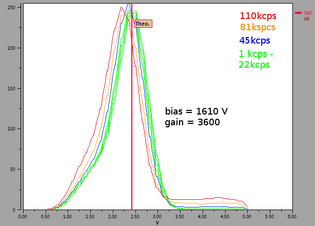
description of above image: Decreasing the bias to level where we still get same amount of counts (in integral mode and maximum gain) allows to charge the feedback capacitor of charge sensitive amplifier less (keeps the capacitor closer to discharged state), thus average load voltage is lower and capacitor voltage cascade transitions are more rapid. As the result CR (OPAMP) differentiators recognize consistently similar cascade transition at capacitor - as from low count rate to medium count rate the mentioned capacitor stays below half of charge voltage where charging slope is very similar in that range (from half charged to near discharged). Thus only high count rate starts to shift the PHA as it starts to enter the higher charge voltage of feedback capacitor.
Why the upper limit is 80-100kcps? There other mechanics kicks in, which is not possible to fix without reducing the shaping time.
There are two competing processes for PHA shift - one is relevant at low-to-medium-high count rates (the average DC component of charge sensitive preampllifier's feedback capacitor) and that can be reduced by reducing bias as shown at above pictures, which makes cascade voltage smaller and thus keeps the capacitor in its 0-50% loaded range. The other process comes at increased density of pulses (in time domain) where chance of registered pulse to start from negative voltage (at after-pulse of previous preceding pulse, as it is two differentiations it produce bipolar pulse) increases tremendously. The only way to fix that is to use faster pulse shaping amplifier (+ following baseline restorer would not hurt), however that would not anyhow fix the problem of PHA shifts made by capacitor average charge level loading above 50%.
The demonstrated way of reducing bias is a way with no hardware modifications. There is some questionable possibility to "fix" that with simple hardware modification - AMPTEK's A203 C.S.P and S.A datasheet describes that by adding additional capacitor in parallel (pins are exposed) to feedback capacitor, the sensitivity of C.S.P can be reduced. I don't know... I need to think about that... It looks for me that feedback resistor value is more deciding at what level capacitors are loaded depending from count rate, and increased capacity would not solve this problem and have just a negative effect of lost P/B (at that step in pipeline) ratio without any advantage at all.
Interestingly, EDS signal pipeline do away with this problem by having no feedback resistor and dropping capacitors charge with resetting circuit kicking-in after voltage gets over some threshold (at the cost of introducing small dead time at C.S.P.; small - input counts reaching 1Mcps produces about 5%). Interestingly XFlash Nano (tailored Bruker detectors for SX100 and SXFive) has very clever designed floating upper reset threshold, where reset happens reaching ~30% of max voltage at low count rates and is raised gradually above 50% (probably even more, had not tested more counts than 1 input Mcps ) with increased count rate. As side effect peak positions shifts a bit toward lower energy at higher count rates (the same effect as observed on PHA shifting on SX WDS). Our SEM equipped Bruker EDS (XFlash 6|30, newer technology than XFlash Nano) feedback capacitors has two reset thresholds (low, and high) - which moves symmetrically away from middle charge point of feedback capacitor and thus shift of peak at different count rates is less noticeable. However that comes at clearly worse resolution than what we see on XFlash Nano on SX'es at small-medium count rates.
There are other wider implications of investigative experiments I came to that above presented conclusions and I will happily share it further (I really should start separate thread dedicated for pipelines of detector-amplification-counting).


 All Electron Probe Micro-Analysts are welcome to register and post!