SF effect of non-contiguous TiO2 phase when measuring Ti in quartz?
Hello all,
I am measuring Ti in individual quartz grains (less than 20 micron long diameter). Problematically, there are small (approximately <5 micron long diameter) TiO2 particles interspersed densely throughout my sample. I did most of my analyses in the centers of crystals that were as far away from the TiO2 phase as possible, ~40 micron away from the nearest particle in most cases. See image below.
I am unfamiliar with modeling complex geometries in Penepma and am hoping that someone has encountered a similar issue and will be able to help. The problem is that the grain of interest is separated from the contaminant crystal in multiple directions by several grain boundaries as well as epoxy. Any help is greatly appreciated,
-Marisa
Hi Marisa,
This sort of thing can get complicated real fast. I try to approach complicated things by first looking at worst case but simplified models. So we already know, using the quick secondary fluorescence GUI for Penfluor/Fanal in Standard (CalcZAF), that if our TiO2 is 40 um away (and I'll assume you're running 15 keV, but maybe not, though it won't be a big effect if you're at 20 keV), the apparent signal from TiO2 is about 0.05 wt% Ti SF effect for an infinite boundary between SiO2 and TiO2. Or 500 PPM. This SiO2/TiO2 SF calculation is described step by step here:
https://probesoftware.com/smf/index.php?topic=58.msg214#msg214But that doesn't apply to your situation of a 5 um (or less) TiO2 inclusion. So we need to pull out the "big gun" and run the Penepma model using the geometric model for an inclusion in a matrix. Instructions for running Penepma are here:
https://probesoftware.com/smf/index.php?topic=322.0But the discussion on modeling inclusions using Penepma is here:
https://probesoftware.com/smf/index.php?topic=59.0Probably should be updated...
So anyway, our next simple but a little more accurate model would be to use Penepma for a 5 um particle inclusion. In this screen shot I created input files for a 5 um TiO2 particle 0, 10, 20, 40 and 80 microns away from the beam position. The 0 um beam position will be in the center of the 5 um TiO2 particle and we can use that as a pseudo standard for the k-ratio (I just realized that I should have added 2.5 microns to all the non-zero distances due to the radius of the 5 um inclusion. Oh well).
Anyway, here is the screen shot, which also shows the basic steps to create the input files and run them from the Penepma batch window:
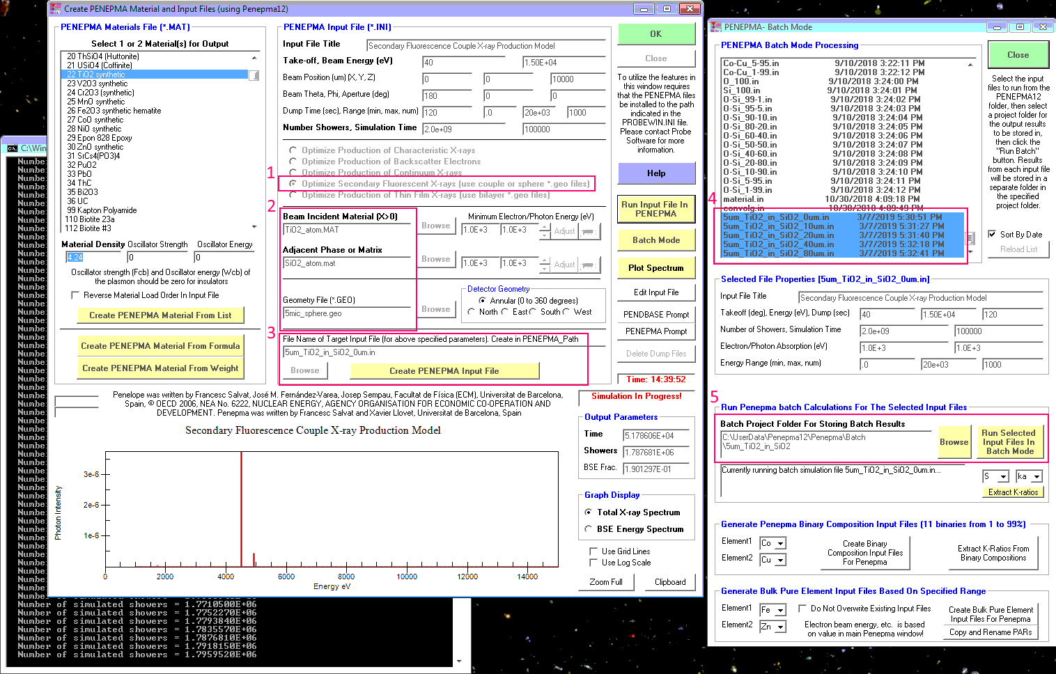
So you should feel free to play around with these Penfluor/Fanal and Penepma GUI interfaces, especially if your samples were run at 20 keV and (oops!), I see from your BSE image that you did. So yes, you should re-do what I'm doing but at 20 keV. But on Monday we can look at the 15 keV models and see what we get.
The point will be that instead of 500 PPM Ti SF effect, we'll get something much smaller. Then the next thing to consider is the fact that you've also got some epoxy in between your SiO2 and your 5 um TiO2 particle. So what will that do?
Well since we know that no characteristic emission lines will be produced from SiO2 that are capable of fluorescing the Ti K edge, we need to only think about continuum emission from the SiO2, and again, only those continuum x-rays that have enough energy to fluoresce the Ti Ka edge in our 5 um TiO2 particle.
To model this in Penepma, will require the use of three materials in our geometric model. Jon Wade and I did create some "trilayer" .geo files but these are intended for a substrate with two thin films deposited on it, so there would some work needed to create a .geo file specifically for your SF situation with SiO2, TiO2 and epoxy.
In the meantime we can imagine what might happen if there was some intervening epoxy between our SiO2 and our TiO2. The continuum x-rays will be produced at the beam incident spot and will travel (roughly) in a spherical direction and until they reach our 5 um TiO2 particle. What will the intervening epoxy do to these high energy continuum x-rays (between 5 and 15 or 20 keV)?
Specifically will these continuum x-rays will tend to be more absorbed by epoxy or less absorbed by epoxy, than SiO2? Nothing like running a physics model I say, so I used Mn Ka traversing 40 um of both SiO2 matrix and epoxy, to see what happens to x-rays that are enough to excite the Ti K edge. Because the Mn Ka is 5.89 keV and the Ti K edge is 4.96 keV so Mn Ka will be a "stand-in" for our high energy continuum x-rays until we do a proper modeling in Penepma with three materials in the proper geometry.
So using the Model Electron and X-Ray Ranges window in CalcZAF, I looked at 40 um of SiO2 for Mn Ka:
Si-O2 = Si1O2 = 60.086g/mol, Si 46.74% O 53.26%
15 keV, 2.7 grams/cm^3
Electron range radius = 2.449919 um
Mn ka, at 15 keV, (6.539 keV edge energy)
X-ray production range radius = 1.837592 um
mn ka absorbed by si = 145.0962
mn ka absorbed by o = 28.13147
Mn ka, x-ray transmission fraction through thickness 40 um (average u/p = 82.8043) = 0.4088993
So about 40% of the Mn Ka x-rays are transmitted through 40 um of SiO2.
And here for Mn Ka in epoxy:
15 keV, 1.16 grams/cm^3
Electron range radius = 5.316666 um
Mn ka, at 15 keV, (6.539 keV edge energy)
X-ray production range radius = 3.987831 um
mn ka absorbed by c = 10.91245
mn ka absorbed by h = .01601
mn ka absorbed by o = 28.13147
mn ka absorbed by cl = 240.9663
Mn ka, x-ray transmission fraction through thickness 40 um (average u/p = 14.06128) = 0.9368385
So about 93% of these Mn Ka x-rays (acting as a "stand-in" for our high energy continuum x-ray that would tend to fluoresce the Ti K edge), will get transmitted through epoxy.
So Mn Ka is a lot less absorbed by epoxy than by SiO2, so whatever SF effect we see in our Penepma modeling, it will be somewhat larger when we run a Penepma model with intervening epoxy. So your question turns out to be very important! We would be underestimating the SF effect if there is some epoxy in between our SiO2 and our TiO2 inclusion!
Now on the other hand, depending on the beam position and TiO2 orientation to the WDS spectrometer, there may also be Bragg defocus effects which will tend to *reduce* the SF effect:
https://www.cambridge.org/core/journals/microscopy-and-microanalysis/article/secondary-fluorescence-in-wds-the-role-of-spectrometer-positioning/94F6F5D3992B37BFBB8B4116BB4605D3Told you it gets complicated!

Let's see what we get on Monday and we can take it from there.
Unless someone has already run these models and can share them with us?


 To post in-line images, login and click on the Gallery link at the top