There may be some confusion here.
Les was originally discussing an emitter (S ka) at the 1% level in a 99% matrix of carbon. So I modeled that as seen in the graph here:
http://probesoftware.com/smf/index.php?topic=47.msg2019#msg2019along with some other emitter-absorber combinations. That's when I called in the "big gun" Nicholas Ritchie at NIST to help explain things.
When Nicholas chimed in with a post labeled "1% C in S at 5 keV and 15 keV" I thought, well maybe he misread our discussion, but I thought I might as well model the emitter at the 99% level even though the matrix effects will obviously be close to 1.
So here is that graph (99% emitters in a 1% absorber matrix):
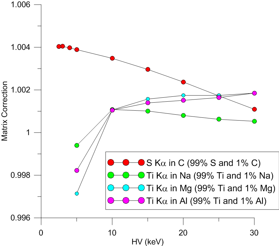
and the Ti ka matrix correction at 10 keV? Well they really are all slightly different- so I didn't use the same value accidentally.
But what the heck occurs at 10 keV for Ti ka in these absorbers?


 If you can't see some "in-line" images in a post, try "refreshing" your browser!