Author Topic: Light Element Crystal Refractive Index Values  (Read 29591 times)

Probeman

  • Emeritus
  • *****
  • Posts: 2856
  • Never sleeps...
    • John Donovan
Light Element Crystal Refractive Index Values
« on: November 21, 2014, 05:13:09 PM »
I'm releasing a version of CalcZAF that has a new window (see Xray | Calculate Spectrometer Position menu in CalcZAF) for calculating spectrometer positions for both JEOL and Cameca instruments as seen here:


To improve this calculation I'd like to:

1. Get suggestions of other spectrometer geometries (different Rowland circles) to implement...

2. I think we should "crowd source" an effort to refine the refractive index values for the light element spectrometer crystals such as PC1 and LDE1 to improve the accuracy of KLM markers on our spectrometer scanning plots.

So here are the crystals that I would like to hear from those that have tried John Fournelle's technique to "back out" the refractive index values for various multi-layer crystals. See the attachment in this link for more info (remember you have to be logged in as a member to see attachments!):

http://probesoftware.com/smf/index.php?topic=197.msg1732#msg1732

LDE45 and PC0 (nominal 45 angstrom 2d)
LDE1 and PC1 (nominal 60 angstrom 2d)
LDE2 and PC2 (nominal 100 angstrom 2d)
LDEB and PC25 (nominal 150 angstrom 2d)
LDEC and PC3 (nominal 200 angstrom 2d)

Please post your own refractive index determinations from your lab...

John F., please feel free to start!

Below I've attached the default CalcZAF crystal table where you can see various efforts to "adjust" the refractive index values for various light element crystals. This file can be copied into your existing Probe for EPMA folder (assuming you haven't made any changes to your original file CRYSTALS.DAT !). New installations will get this CRYSTALS.DAT file automatically.
« Last Edit: November 21, 2014, 05:26:31 PM by Probeman »
The only stupid question is the one not asked!

Julien

  • Professor
  • ****
  • Posts: 84
  • The truth is out there...
    • Geoloweb - J. Allaz personal website
Re: Light Element Crystal Refractive Index Values
« Reply #1 on: November 21, 2014, 08:08:51 PM »
I might try to get some value on our vintage JEOL-8600 with LDEC, LDEB and LDE1 crystals, but meanwhile, here are some values I randomly found on the web or in the literature (not even sure if I can find back the exact source of the data...):

Crystal (2d) = Refractive index "k"

PC0 (45 Å) = 0.006
LDE45 (45 Å) = 0.01

PC1 (60.6 Å) = 0.00832
LDE1 (60 Å) = 0.01
LDE1H (62.5 Å) = 0.008

PC2 (95 Å) = 0.021
LDE2 (98 Å) = 0.01
ODPb (100.7 Å) = 0.0175

PC25 (147.66 Å) = 0.02
LDEB (145 Å) = 0.01

PC3 (200.5 Å) = 0.02
LDE3 (200 Å) = 0.02
LDEC (200 Å) = 0.04


Julien
« Last Edit: November 21, 2014, 08:48:41 PM by Julien »

Probeman

  • Emeritus
  • *****
  • Posts: 2856
  • Never sleeps...
    • John Donovan
Re: Light Element Crystal Refractive Index Values
« Reply #2 on: November 21, 2014, 10:04:21 PM »
I might try to get some value on our vintage JEOL-8600 with LDEC, LDEB and LDE1 crystals, but meanwhile, here are some values I randomly found on the web or in the literature (not even sure if I can find back the exact source of the data...):

Crystal (2d) = Refractive index "k"

PC0 (45 Å) = 0.006
LDE45 (45 Å) = 0.01

PC1 (60.6 Å) = 0.00832
LDE1 (60 Å) = 0.01
LDE1H (62.5 Å) = 0.008

PC2 (95 Å) = 0.021
LDE2 (98 Å) = 0.01
ODPb (100.7 Å) = 0.0175

PC25 (147.66 Å) = 0.02
LDEB (145 Å) = 0.01

PC3 (200.5 Å) = 0.02
LDE3 (200 Å) = 0.02
LDEC (200 Å) = 0.04

Hi Julien
This is useful.  Let the testing begin!

By the way, I checked John Fournelle's early calculations and I'm confused.  Did the graph labels for F ka and P ka III get swapped or did I screw up the calculation...?

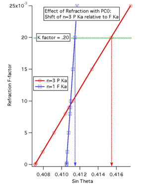
The point is, John Fournelle made this graph some some time ago, and he showed that depending on the value of the PC0 refractive index, the P Ka 3rd order line will show up on one side *or* the other side of the F Ka line (and hence the corresponding spectral interference position!). But the F ka line in my calculation shows the larger change compared to P ka 3rd order for different refractive index values.


Anyway, is the refractive index of a PC0 (45 angstrom 2d) really 0.02?  According to John F.'s measurements, the answer is yes.

Here is the calculation from the new CalcZAF window:
Spectro position for f  ka on PC0 (160 mm), is 41542 (with refractive index correction, k= 0.02)
Spectro position for p  ka (III) on PC0 (160 mm), is 41145 (with refractive index correction, k= 0.02)

The point is that with a large enough refractive index (0.02), the P Ka 3rd order line will shift relative to the F Ka 1st order line, enough to fall on the other side of the F Ka position!  E.g.,

Spectro position for f  ka on PC0 (160 mm), is 41542 (with refractive index correction, k= 0.02)
Spectro position for p  ka (III) on PC0 (160 mm), is 41145 (with refractive index correction, k= 0.02)

Spectro position for f  ka on PC0 (160 mm), is 41122 (with refractive index correction, k= 0.01)
Spectro position for p  ka (III) on PC0 (160 mm), is 41099 (with refractive index correction, k= 0.01)

Spectro position for f  ka on PC0 (160 mm), is 40711 (with refractive index correction, k= 0)
Spectro position for p  ka (III) on PC0 (160 mm), is 41053 (with refractive index correction, k= 0)

A little help please!

Edit by John: Ok, as Julien has confirmed in the next post, John Fournelle's plot labels in the graph above are reversed. 
« Last Edit: October 31, 2023, 07:41:47 AM by Probeman »
The only stupid question is the one not asked!

Julien

  • Professor
  • ****
  • Posts: 84
  • The truth is out there...
    • Geoloweb - J. Allaz personal website
Re: Light Element Crystal Refractive Index Values
« Reply #3 on: November 22, 2014, 09:55:24 AM »
I agree with John D., I think the label for P Ka (n=3) and F Ka (n=1) in John F. graphic have been inverted. The opposite should be observed. I have recompute the same calculation, and here is the result:


Attached is the XL spreadsheet I used for this calculation. It also contains the list of element / standard / X-ray line / order that John F. suggest to use for these tests (see his PPT under the link posted by John D: http://probesoftware.com/smf/index.php?topic=197.msg1732#msg1732). Hopefully this will help each of us to determine the refractive index for our crystals.

Aside of this, I wonder... Assuming that the monochromator for a specific microprobe of a same "batch" (e.g., all SX-100 or all JEOL-8200) have been made at the same factory, shouldn't we assume a very similar refractive index? And actually, assuming that the refractive index is depending on the material used, shouldn't we expect the exact same refractive index (or very close) for the same monochromator type? In other word: what are the parameters that control this refractive index?
  • The quality of the monochromator (can vary depending on the manufacturer of the monochromator)?
  • The material used in the monochromator?
  • The exact monochromator spacing (seems that k increase with 2d)?

Julien
« Last Edit: November 30, 2014, 11:43:22 AM by Julien »

Probeman

  • Emeritus
  • *****
  • Posts: 2856
  • Never sleeps...
    • John Donovan
Re: Light Element Crystal Refractive Index Values
« Reply #4 on: November 22, 2014, 10:19:39 AM »
  • The quality of the monochromator (can vary depending on the manufacturer of the monochromator)?
  • The material used in the monochromator?
  • The exact monochromator spacing (seems that k increase with 2d)?
Thanks Julien.

The basic problem as John F. and I have surmised is that the manufacturers calculate the 2d spacing *without* accounting for the refractive index of the materials in the multi-layers.  The typical material used in the manufacturing of the multi-layers is quite high Z (e.g., W/Si), compared to say LiF and that is why the refractive index is so high for these "crystals".

So when the purchased multi-layer crystal is reported as 59 angstroms 2d, that is *not* (so far as we have seen) accounting for the refractive index.

John Fournelle's class exercise:

http://probesoftware.com/smf/index.php?topic=197.msg1732#msg1732

is to utilize multiple order lines to determine both the actual 2d and the effective refractive index for these multi-layer crystals.
« Last Edit: November 30, 2014, 02:18:13 PM by Probeman »
The only stupid question is the one not asked!

Julien

  • Professor
  • ****
  • Posts: 84
  • The truth is out there...
    • Geoloweb - J. Allaz personal website
Re: Light Element Crystal Refractive Index Values
« Reply #5 on: November 22, 2014, 11:59:11 AM »
Yes, John, I totally acknowledge John F exercise, indeed the attached spreadsheet should help any user to calculate this optimum k (and 2d) to yield the correct sin-theta. The game, if I understand correctly, is to change the k (and 2d) to match the calculated and the measured sin-theta position of some key peaks. In the spreadsheet, the first sheet contains the list of lambda positions for the element and X-ray line and line order suggested by John F exercise.

If I have time, maybe I'll work on a macro to automatically calculate the optimum k and 2d, using a double-iterative loop to minimize the difference between the theoretical and calculated sin-theta peak position. However, this might be tricky...

Anyway, aside of this, on a mathematical point of view, one can calculate the difference in sin(theta) between the "classical" Braggs law and the revised Braggs law that include the refractive index. This difference (sin(theta) from "classical" MINUS sin(theta) from "revised") can be expressed as follows:

Delta(sin-theta) = k * n * (lambda) / (2d * (n^2 - k))

So when n increases, for the same value of k, the difference of sin-theta should be LESS: assuming delta(sin-theta) is proportional to k*n/(n^2 - k), with (n^2 - k) > k*n, since k is always < 1).

Do you or John F have already some data (peak position of one or more element(s) with different diffraction order on the same monochromator) so I could "play" with it (i.e., trying to build this XL macro to calculate an optimum 2d and k)?

J.

Probeman

  • Emeritus
  • *****
  • Posts: 2856
  • Never sleeps...
    • John Donovan
Re: Light Element Crystal Refractive Index Values
« Reply #6 on: November 22, 2014, 12:01:15 PM »
Ok, new version of CalcZAF (v. 10.5.3) allows us to "play" with the refractive index to see the effect on spectrometer position.


Edit by John: using this dialog one can calculate nominal spectrometer positions for JEOL (L-value) and Cameca (sin theta) with or with the Bragg refractive index effect.
« Last Edit: July 02, 2015, 08:53:30 AM by John Donovan »
The only stupid question is the one not asked!

Julien

  • Professor
  • ****
  • Posts: 84
  • The truth is out there...
    • Geoloweb - J. Allaz personal website
Re: Light Element Crystal Refractive Index Values
« Reply #7 on: November 22, 2014, 12:14:31 PM »
BTW, do you have an option in CalcZAF for the 100 mm Rowland circle on JEOL (H-type spectrometer)? I'm surprised Paul would not have asked you that already, as it seems he is a great fan of these spectrometers that can give up to 6x more counts than a regular spectrometer with small area crystals...

J.

Probeman

  • Emeritus
  • *****
  • Posts: 2856
  • Never sleeps...
    • John Donovan
Re: Light Element Crystal Refractive Index Values
« Reply #8 on: November 22, 2014, 02:55:29 PM »
BTW, do you have an option in CalcZAF for the 100 mm Rowland circle on JEOL (H-type spectrometer)? I'm surprised Paul would not have asked you that already, as it seems he is a great fan of these spectrometers that can give up to 6x more counts than a regular spectrometer with small area crystals...
Yes, with some tradeoff in spectral resolution.

This suggestion is exactly what I am looking for.  See point #1 in this post:

http://probesoftware.com/smf/index.php?topic=375.msg1971#msg1971

So 100mm Rowland for JEOL.  Any others I should add?
The only stupid question is the one not asked!

Julien

  • Professor
  • ****
  • Posts: 84
  • The truth is out there...
    • Geoloweb - J. Allaz personal website
Re: Light Element Crystal Refractive Index Values
« Reply #9 on: November 23, 2014, 02:09:42 PM »
Here is a small macro file that should (hopefully?) ease the determination of the optimum k and 2d. This macro use the "solver" of microsoft Excel, and you will need to activate it (see the PDF help document for instructions on how to activate the Microsoft Excel Solver). I've tested this on my mac (Office 2011) and on Windows 7 (Office 2013). Both worked fine.

All you need are peak position measured on a specific spectrometer / monochromator. A list of recommended element / X-ray line to use for this test is given in this spreadsheet (based on suggestions from John Fournelle).

The spreadsheet determines the difference between the measured and calculated (theoretical) peak position using the Braggs law and the refractive index (k). The solver (macro) is then used to yield an average of peak position differences of zero and to minimize the standard deviation of these differences.

Let me know if this works!

Julien

Philipp Poeml

  • Professor
  • ****
  • Posts: 222
Re: Light Element Crystal Refractive Index Values
« Reply #10 on: November 24, 2014, 01:55:49 AM »
Yes, please add Cameca 180 mm spectrometers.

Thanks!

Julien

  • Professor
  • ****
  • Posts: 84
  • The truth is out there...
    • Geoloweb - J. Allaz personal website
Re: Light Element Crystal Refractive Index Values
« Reply #11 on: November 24, 2014, 04:17:35 PM »
Alright, after a few hours of WDS scan on grand'ma JEOL-8600 (26 years old!), I got some results on the 2d-k evaluation on my available multilayers. Results on LDE1 (60 Å) are pretty consistant, independent on the X-ray line / order I choose for the regression. However, I cannot tell this for the other two large-2d spectro I have (LDEC ~100Å and LDEB ~150Å). Here it is (details in the spreadsheet):

- LDE1 (60 Å): 2d = 61.3 Å / k = 0.013
- LDEC (100 Å): 2d = 102.5 Å / k = 0.028
- LDEB (150 Å): 2d = 149.2 Å / k = 0.035

Now, if I exclude some "badly defined (high order) peaks"...
- LDE1 (60 Å): 2d = 61.3 Å / k = 0.014
- LDEC (100 Å): 2d = 102.8 / k = 0.031
- LDEB (150 Å): 2d = 150.0 / k = 0.041

Note that these values are NOT corrected for possibly dynamic (mechanical) shift... I cannot easily verify this (suggestions are welcome for this matter...), although if I assume a shift similar to the other crystals available (PET and TAP for spectrometer with LDEC and LDEB, TAP for spectrometer with LDE1), then here are the results:
- LDE1 (60 Å): 2d = 61.4 Å / k = 0.013
- LDEC (100 Å): 2d = 102.7 Å / k = 0.028
- LDEB (150 Å): 2d = 149.4 Å / k = 0.035
("of course" this shift chiefly affects the 2d of the crystal, not so much the k...)

See the XL spreadsheets for the results (one is a modified copy of the XL macro I wrote - see my former comment, the other are the acquisition results [peak positions]; these results are NOT corrected for possible dynamic shift, which are in the order of 0.1-0.2 mm on my JEOL-8600). I got these results using a high-beam current (most of them 200 nA, some 100 nA), with 2 to 4 seconds counting time (longer on high-order lines), and with a step of 0.1 mm or 0.00035 sin-theta (some 0.25 mm = 0.00090 sin-theta). These could have been refined using a smaller step size and longer counting time, but I did not have enough time to do this today... Also, keep in mind that ALL my monochromators are "normal" area monochromator... Hence the difficulty to get good precision on X-ray line above 3rd-4th order... Even on pure metals for L-lines...

@John Fournelle: maybe, can you suggest the conditions you've used for your WDS scan?

And for comparison, here are the data that John Fournelle mention in his PowerPoint (slide 19):
- PC0 (45 Å): old = 44 Å, 0.01483 => NEW: 44 Å, 0.01
- PC1 (60 Å): old = 61 Å, 0.01 => NEW: 62.1 Å, 0.02
- PC2 (100 Å): old = 95.2 Å, 0.013 => NEW: 98.5 Å, 0.033
- PC3 (200 Å): old = 200 Å, 0.01 => NEW: 204 Å, 0.04

Comments and additional data from other labs are more than welcome!

Julien

Probeman

  • Emeritus
  • *****
  • Posts: 2856
  • Never sleeps...
    • John Donovan
Re: Light Element Crystal Refractive Index Values
« Reply #12 on: November 24, 2014, 05:55:08 PM »
Yes, please add Cameca 180 mm spectrometers.
Of course since Cameca spectrometers read out directly in sin-theta units, the spectrometer positions for the 160 and 180 mm FC spectrometers are the same.

In fact even JEOL has the 100mm spectrometer positions read out as though they were a 140mm Rowland circle spectrometer (according to Paul Carpenter JEOL seems to be handling the difference in the spectrometer micro-code)- because of course they should be different in L-unit values!).  Anyway, I added them to the list to make that clear as seen here:


Here is the output for all 4 options for Fe ka:

Spectro position for fe ka on LIF (140 mm), is 134.7153 (without refractive index correction)
Spectro position for fe ka on LIF (160 mm), is 48113 (without refractive index correction)
Spectro position for fe ka on LIF (140 mm), is 134.7153 (without refractive index correction)   <-  should say 100mm but it's as though it was a 140mm!
Spectro position for fe ka on LIF (180 mm), is 48113 (without refractive index correction)  <-  should say 180mm but it's as though it was a 160mm!
« Last Edit: December 03, 2015, 02:45:12 PM by Probeman »
The only stupid question is the one not asked!

David Steele

  • Professor
  • ****
  • Posts: 33
Re: Light Element Crystal Refractive Index Values
« Reply #13 on: November 25, 2014, 06:50:27 PM »
I've recently measured the d-spacings for the 3 LDE crystals on our 8530F in an attempt to have PfE display the KLM markers on Plot!ted wavescans much closer to the real peak positions on our probe.  I've updated and saved the probe.ini file.  Yesterday I created a brand new MDB file (after updating the ini file) on the presumption that the updated d-spacings would be used in the new mdb.  Errr, yes AND no!!!

I've attached a screen dump from the log window.....

Why are the CRY2D values correctly updated for F on LDE1, B on LDEB, N on both LDE1 and LDE2 (I didn't change the TAP d), BUT BOTH d spacings for O on LDE1 and LDE2 using the 'old' (inappropriate, default/book) values??

Got me beat this one!!!

In addition to updating the d-spacings in the ini file, I also changed a few of the default settings, e.g. the Magnification (analytical), Magnification (default) and Magnification (Imaging) BUT these haven't been updated either!!

PS: Karsten, I found out why our system wasn't using the last unknown's settings for wavescans....  The UseLastUnknownAsWavescanSetup flag in the ini file was set to 0.  I also updated that in the .ini, but that hasn't been implemented either.

SO, I've updated and saved the .ini file (in Notepad++).  What else do I HAVE to do to get PfE to use this new updated .ini file??

(somewhat frustrated by PfE NOT using the new info...)

John Donovan

  • Administrator
  • Emeritus
  • *****
  • Posts: 3304
  • Other duties as assigned...
    • Probe Software
Re: Light Element Crystal Refractive Index Values
« Reply #14 on: November 25, 2014, 06:59:37 PM »
SO, I've updated and saved the .ini file (in Notepad++).  What else do I HAVE to do to get PfE to use this new updated .ini file??

(somewhat frustrated by PfE NOT using the new info...)
Hi David,
Glad to see you getting into the software... but the reason is because it is a scientific "no-no" to change parameters for existing data!

Create a new run and the new values will be used.
john

PS I think you mean you edited the CRYSTALS.DAT file, not the probewin.ini file...
« Last Edit: November 25, 2014, 07:19:29 PM by John Donovan »
John J. Donovan, Pres. 
(541) 343-3400

"Not Absolutely Certain, Yet Reliable"