Author Topic: PHA issues  (Read 16338 times)

wrigke

  • Professor
  • ****
  • Posts: 40
PHA issues
« on: August 13, 2013, 11:11:16 AM »

I have a couple of questions about setting PHA's on my Cameca probe.  I have four spectrometers; numbers 1 and 4 are low pressure while numbers 2 and 3 are high pressure.  In my PFE files it says that the default biases are 1300, 1860, 1850 and 1425, respectively.  There are then four different settings for default gain, which I assume are individual gain settings for each of the four crystals in each spectrometer.  Do these default bias settings seem appropriate for the low pressure spectrometers? 

Secondly, I was setting up a measurement of lanthanide elements and I put Nd Lb and Pr Lb on Spec 2 using a quartz crystal.  Using the PFE bias scan, the optimum bias appeared to be around 1800 with a gain of around 200.  I then put Sm La on Spec 3 also using a quartz crystal.  Again, using the PFE bias scan, the optimum bias was 1665 with a gain of 680.  I can't understand why Sm PHA is so very different from Nd and Pr, so I then ran Sm La on Spec 2 using quartz and the optimum bias was 1810 with a gain of 210.  What might be going on with the PHA between Spec 2 and Spec 3?  The gas pressure is the same for both.

Cheers,
Karen

John Donovan

  • Administrator
  • Emeritus
  • *****
  • Posts: 3260
  • Other duties as assigned...
    • Probe Software
Re: PHA issues
« Reply #1 on: August 13, 2013, 11:42:58 AM »
I have a couple of questions about setting PHA's on my Cameca probe.  I have four spectrometers; numbers 1 and 4 are low pressure while numbers 2 and 3 are high pressure.  In my PFE config files it says that the default biases are 1300, 1860, 1850 and 1425, respectively.  There are then four different settings for default gain, which I assume are individual gain settings for each of the four crystals in each spectrometer.  Do these default bias settings seem appropriate for the low pressure spectrometers? 

Hi Karen,
The Cameca detectors typically run bias levels around here:

Low (1 PSIG or 2 PSIA) pressure detectors (with TAP crystals) bias voltage range 1200 - 1300 or so.
High (2 PSIG or 3 PSIA) pressure detectors (with LIF crystals) bias voltage range 1800 - 1900 or so

where PSIG is pounds per square inch gauge and PSIA is psi absolute (referenced to vacuum).

Lower energy x-ray lines benefit from a little extra bias voltage, so for example, Si Ka on a high pressure detector (e.g., PET crystal) will often get a better count rate at a bias voltage of over 1900 volts.

Note that in the PFE config files the default bias voltage and gain can be set differently for each crystal on lines 54 to 65 of the SCALERS.DAT file.

Secondly, I was setting up a measurement of lanthanide elements and I put Nd Lb and Pr Lb on Spec 2 using a quartz crystal.  Using the PFE bias scan, the optimum bias appeared to be around 1800 with a gain of around 200.  I then put Sm La on Spec 3 also using a quartz crystal.  Again, using the PFE bias scan, the optimum bias was 1665 with a gain of 680.  I can't understand why Sm PHA is so very different from Nd and Pr, so I then ran Sm La on Spec 2 using quartz and the optimum bias was 1810 with a gain of 210.  What might be going on with the PHA between Spec 2 and Spec 3?  The gas pressure is the same for both.

1665 is way too low for a high pressure detector, so set it to 1850 and run the gain scan.

Also why are you using beta lines?  They are low precision and less accurate in the matrix correction.  Use the alpha lines and specify the interferences as described starting on page 172 of the Advanced Topics manual.
John J. Donovan, Pres. 
(541) 343-3400

"Not Absolutely Certain, Yet Reliable"

wrigke

  • Professor
  • ****
  • Posts: 40
Re: PHA issues
« Reply #2 on: August 13, 2013, 12:06:29 PM »
John,

In reference to the high P detector set at 1665, I did run the bias scan, which showed the maximum at 1665.  I then set the bias to 1665 and ran the gain scan and set the gain to 680.  When I ran this Sm line on the other high pressure detector (choosing the PHA in the manner I just described), I got results that you expect.  The question is, what's up with the detector?  Or am I not correctly using the PHA scan windows?

Karen

John Donovan

  • Administrator
  • Emeritus
  • *****
  • Posts: 3260
  • Other duties as assigned...
    • Probe Software
Re: PHA issues
« Reply #3 on: August 13, 2013, 01:27:23 PM »
The bias scan first sets the baseline and window filters to a narrow band in the middle of the PHA energy range and then scans the bias voltage.

I think what might have happened is that if your gain was set too high to begin with, then the counts went out of the baseline/window band range as the bias voltage was increased.

It's a bit of a chicken or the egg thing. Which do you set first?  I think my suggestion of 1200-1300 for low pressure and 1800-1900 for high pressure detectors will give good results.
John J. Donovan, Pres. 
(541) 343-3400

"Not Absolutely Certain, Yet Reliable"

Philipp Poeml

  • Professor
  • ****
  • Posts: 219
Re: PHA issues
« Reply #4 on: August 14, 2013, 06:17:08 AM »
Hi Karen,

if you want to know my opinion, just leave the Bias of SP1+4 at 1300 and SP2+3 at 1870. Do play with the gain only.

As for the PHA measurement: I prefer Peaksight in 99% of the cases. It is much faster, because they use some sort of multichannel measurement system, at least that's what some technician explained to me. I adjust my gains in PeakSight and then import the value into PfE. There is a "read pha settings" button.

Cheers
Ph
« Last Edit: August 14, 2013, 06:23:45 AM by Philipp Pöml »

Philipp Poeml

  • Professor
  • ****
  • Posts: 219
Re: PHA issues
« Reply #5 on: August 14, 2013, 06:19:57 AM »
Hi John,

why we sometimes measure Beta lines? Well, for example: The U Mb sits on top of the Pu Ma. Now, our sample is about 99 wt. % UO2, and 1 wt. % PuO2... What do you think? Correcting for the overlap or just measuring the Pu Mb line?

Cheers
Philipp

John Donovan

  • Administrator
  • Emeritus
  • *****
  • Posts: 3260
  • Other duties as assigned...
    • Probe Software
Re: PHA issues
« Reply #6 on: August 14, 2013, 08:04:15 AM »
As for the PHA measurement: I prefer Peaksight in 99% of the cases. It is much faster, because they use some sort of multichannel measurement system, at least that's what some technician explained to me. I adjust my gains in PeakSight and then import the value into PfE. There is a "read pha settings" button.
Ph

I agree that the new multi channel analyzer PHA is faster which is why I have requested that Cameca provide the documentation for this command to us.  As soon as they do...  I will implement it.
« Last Edit: August 14, 2013, 08:10:57 AM by John Donovan »
John J. Donovan, Pres. 
(541) 343-3400

"Not Absolutely Certain, Yet Reliable"

John Donovan

  • Administrator
  • Emeritus
  • *****
  • Posts: 3260
  • Other duties as assigned...
    • Probe Software
Re: PHA issues
« Reply #7 on: August 14, 2013, 08:10:26 AM »
why we sometimes measure Beta lines? Well, for example: The U Mb sits on top of the Pu Ma. Now, our sample is about 99 wt. % UO2, and 1 wt. % PuO2... What do you think? Correcting for the overlap or just measuring the Pu Mb line?

I was referring to the L family where the Lb is about 40% the intensity of the La, where as the M family is more equal (Ma:Mb is about 100:60).

But yes, that is a nasty example.  But try it both ways on standards and post your results here for us to see. I would be very interested.
John J. Donovan, Pres. 
(541) 343-3400

"Not Absolutely Certain, Yet Reliable"

Philipp Poeml

  • Professor
  • ****
  • Posts: 219
Re: PHA issues
« Reply #8 on: August 14, 2013, 11:07:32 AM »
It would be fantastic if PfE used this multi channel thing. I will ask Cameca about this next time I'll talk to them. Is it possible to reverse engineer that?

Ok, I also think it might be cool to test which one is better, Mb or overlap correction. But how would I test the quality of the data?

What about  L lines then? There are some cases where we use Lb, for Cs for example. There is some nasty overlap.

My question is, is it always possible to correct? In theory yes, right? As long one has the proper standards for measuring the correction values. It would be interesting to try this on Cs for example. I should check how many counts I will gain using Cs La.

Anyway, in general we have good experiences with beta lines. But we work at funny conditions anyway, 250 nA and 50 sec counting is standard...

Cheers
Ph

John Donovan

  • Administrator
  • Emeritus
  • *****
  • Posts: 3260
  • Other duties as assigned...
    • Probe Software
Re: PHA issues
« Reply #9 on: October 22, 2013, 02:19:21 PM »
It would be fantastic if PfE used this multi channel thing. I will ask Cameca about this next time I'll talk to them. Is it possible to reverse engineer that?

No need, Cameca has provided the protocols for the PHA MCA call, so I will implement it ASAP.

Quote from: Philipp Pöml
Ok, I also think it might be cool to test which one is better, Mb or overlap correction. But how would I test the quality of the data?

I would try some standards. There will be lower precision with the Mb line since the intensity is lower. As for the interference correction it is worth mentioning that when you have a significant overlap to correct, be sure to use the Use Unknown Count Time For Interf. Std option in the Acquisition Options dialog as seen here:


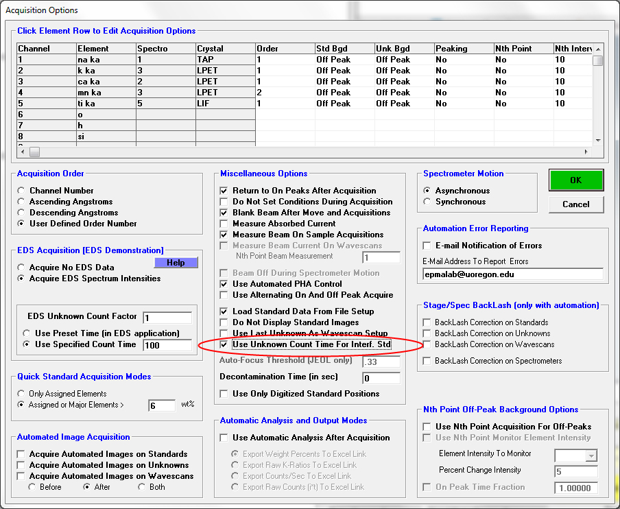
This allows the program to calibrate the interference overlap using the same precision as your unknowns. Normally these are the same, but if the element in the unknown is at a minor or trace level and therefore one is utilizing the Unknown Count Factor feature to count longer on the unknowns than the standards, this will insure that the precision of the interference correction is equal to the precision of the unknown measurement.

Quote from: Philipp Pöml
What about  L lines then? There are some cases where we use Lb, for Cs for example. There is some nasty overlap.

My question is, is it always possible to correct? In theory yes, right? As long one has the proper standards for measuring the correction values. It would be interesting to try this on Cs for example. I should check how many counts I will gain using Cs La.

I have not found a situation where the quantitative interference correction in PFE did not work as expected as long as proper standards are available for the interference overlap calibration.

I agree that oxygen interferences can be problematic, for example, Ti Lb interfering with oxygen because it is difficult to find a Ti standard that does not have some bulk oxygen. However, now that we have obtained some iodine vapor grown Ti crystals, as long as we polish the standard mount just prior to measurement, we can correct for this overlap very nicely.

  Interference by Al SKBX     III   at  23.8690 =     14.5%
  Interference by Ti LB3            at  23.8890 =    676.2%
  Interference by Ti LB4            at  23.8890 =    354.4%
  Interference by Al KB1      III   at  23.9500 =     17.2%
« Last Edit: October 22, 2013, 06:59:55 PM by John Donovan »
John J. Donovan, Pres. 
(541) 343-3400

"Not Absolutely Certain, Yet Reliable"

jared.wesley.singer

  • Post Doc
  • ***
  • Posts: 17
Re: PHA issues
« Reply #10 on: September 25, 2014, 01:55:57 PM »
My following comments are more general about PHA, so I have redirected this from the specific discussion of the MCA PHA feature.

Initially looking like a "noisy" PHA scan, the little spikes look systematic as I increase the points and count time using traditional PHA acquisition.  These are all on the same detector using kyanite.

Aluminum on TAP

Silicon on TAP

and Silicon on PET


If the distribution of photon energies is infinitesimally narrow, what factors shape the pulse-amplitude distribution? The Goldstein et al. Bible (p.287) gives a rule of thumb for appropriate detector resolution being (FWHM*100)/meanVolts=15-20%.   Since my Si(TAP) pulse-amplitude distribution is about 1.5*100/4~40% and asymmetric, Goldstein et al. says "failure of the electronics or degradation of the counter tube". 

Goldstein et al. recommends hooking up an oscilloscope.   Does anyone have recommendations to systematically assess detector health using PFE or StartWin?  Any thoughts on the little spikes?


John Donovan

  • Administrator
  • Emeritus
  • *****
  • Posts: 3260
  • Other duties as assigned...
    • Probe Software
Re: PHA issues (MCA vs. Trad.)
« Reply #11 on: October 29, 2014, 12:13:00 PM »
Recently Julie was teaching a lab and was trying to show the Ar escape peak in a PHA scan, but every time she ran one she got something like this:


I poked around and then finally remembered something about this when I first implemented the MCA PHA acquisition feature in the Sx100, so I changed the PHA acquisition type back to "traditional" and now we get this:


The original topic discussing this hardware is here:

http://probesoftware.com/smf/index.php?topic=217.0

Clearly the MCA PHA is lower energy resolution, but does that explain why the Ar escape peak isn't visible with the MCA PHA acquisition?
John J. Donovan, Pres. 
(541) 343-3400

"Not Absolutely Certain, Yet Reliable"

John Donovan

  • Administrator
  • Emeritus
  • *****
  • Posts: 3260
  • Other duties as assigned...
    • Probe Software
Re: PHA issues
« Reply #12 on: March 18, 2018, 09:53:53 AM »
This is another old topic but since it's looking at Cameca PHA hardware/software, I think it is relevant.  I should first mention that Gareth Seward recently pointed out to me that we had never actually implemented the Adjust PHA button in Probe for EPMA!  That is, the button was there, but it didn't do anything!    :-[

We had added the Adjust PHA button several years ago (along with the SX100/SXFive MCA PHA code), but we must have gotten distracted by something else and never actually connected the GUI to the firmware call which has been implemented in the driver all that time.  However, since Cameca was kind enough to provide the firmware call to us, and now that Gareth has prodded me, we figured let's add the adjust PHA firmware call to the GUI as seen here:


But to be absolutely honest I've always just tweaked my PHA parameters manually, so I really have no experience with this "adjust PHA" call to the Cameca's MachLib library.  When I tested it on my SX100, it takes just a second or two and seems to modify the baseline and window a bit.  But that was on a PHA scan that was pretty much already good.  I haven't tried it with badly tuned PHA parameters yet. 

So my question to you Cameca folks is:  what exactly does this Adjust PHA call do?  Does it only mess with the baseline and window values, or does it also modify the bias and gain values?  Any caveats in its use?
« Last Edit: April 13, 2020, 10:08:41 PM by John Donovan »
John J. Donovan, Pres. 
(541) 343-3400

"Not Absolutely Certain, Yet Reliable"

Probeman

  • Emeritus
  • *****
  • Posts: 2822
  • Never sleeps...
    • John Donovan
Re: PHA issues
« Reply #13 on: May 15, 2018, 12:42:35 PM »
Does anyone know why we're seeing a high energy tail on some of our detectors, but not others?

For example, here is a PHA distribution for Ti Ka on spec 1 PET:


and here is a PHA distribution for Ti Ka on spec 3, also PET:


At first I thought the tail might be from the fact that spec 3 is a 2 atm detector, but no that doesn't seem to be it. Here is a PHA distribution for spec 2 which is a low pressure detector just like spec 1:


Any ideas?
« Last Edit: April 13, 2020, 09:12:13 AM by John Donovan »
The only stupid question is the one not asked!

neko

  • Professor
  • ****
  • Posts: 66
Re: PHA issues
« Reply #14 on: October 19, 2018, 10:28:57 AM »
I've got a good one for ya - here's two PHA scans, this time is the relative verification peaks for PET and LIF, but on the same spectrometer. PET looks a little weird but not obviously horrible, and then LIF has a nice little extra peak on the right side of the primary peak. It wasn't like this in the past, but we don't use LIF on that spectrometer very often (of our two LPET/LLIF spectrometers, this one is less sensitive for LIF than the other and vice versa for PET).

the PHA for Ca Ka/LPET is 1850/897 - not bad but a little low. The PHA for Fe Ka/LIF is 1849/400. The other LLIF crystal we have has a bias about 25 values higher.

I assume I need to adjust the gas flow again, ever so slightly.