Author Topic: Detection limits and error in the case of peak interference  (Read 8421 times)

Spratt NHM

  • Graduate
  • **
  • Posts: 8
Detection limits and error in the case of peak interference
« on: April 15, 2014, 06:51:42 AM »
I have a question about the calculation by software (s) of detection limits in the case of elements determined in the presence of peak interferences. I have attached a rough diagram which should make my ramblings a bit more coherent. My current understanding is that detection limits are determined by statistics relating the No. of counts of the background (ie background count measurements under the peak as determined by measurement of off peaks and or slope determinations) , the number of counts obtained from the standard and a measurement of standard deviation of counts above background. In the case of a peak overlap as that shown in my diagram P(I) on a determined peak (P), the background of the measured peak is Background + overlap. Is this value used in the calculation of the detection limits and error when peak overlap correction is done automatically in software. By software I mean manufacturers and Probesoftware as I have not seen this mentioned in any manuals??

Probeman

  • Emeritus
  • *****
  • Posts: 2856
  • Never sleeps...
    • John Donovan
Re: Detection limits and error in the case of peak interference
« Reply #1 on: April 16, 2014, 01:26:25 PM »
Is this value used in the calculation of the detection limits and error when peak overlap correction is done automatically in software. By software I mean manufacturers and Probesoftware as I have not seen this mentioned in any manuals??
Hi John,
You are exactly correct I think. No one that I know of includes the precision of the interference correction intensity in the total analytical precision. Ideally one would include this estimate of precision in the analytical error calculation along with the P and B of the standard and the P and B of the unknown.

However, if we assume the interference is on the same order or less as the background correction (which it often is), the precision contribution is similar to what we already have. But it is a good point and I will have to look at adding that...   8)

In any event, in order to prevent the interference correction statistics from swamping the normal analytical statistics, I have added an option to the Probe for EPMA software (that you have) as seen here:


This option ensures that if a standard intensity is needed for an interference correction, the software will automatically acquire that interference standard intensity using the same count time as the unknown sample.
The only stupid question is the one not asked!

Probeman

  • Emeritus
  • *****
  • Posts: 2856
  • Never sleeps...
    • John Donovan
Re: Detection limits and error in the case of peak interference
« Reply #2 on: April 16, 2014, 04:46:55 PM »
I should also mention that aside from precision issues, the major issue for interference correction is accuracy. But because the interference correction in Probe for EPMA is fully matrix corrected, one can get excellent results in almost any situation, for example these results for Rb interfered by Si (and corrected) as seen here:


The interference corrected results are all zero within precision. Without the quantitative interference correction,  the Rb concentration would be around 0.3 to 0.4 percent. Important when trying to determine trace Rb in feldspars for example!
The only stupid question is the one not asked!

Brian Joy

  • Professor
  • ****
  • Posts: 296
Re: Detection limits and error in the case of peak interference
« Reply #3 on: April 17, 2014, 07:39:18 PM »
Note that K Ka(2) is also a potential source of interference for this particular problem.  I can't remember exactly what the sine(theta) limit is for CAMECA spectrometers, but JEOL users have the option of using PETH to measure Rb La.  Not only are the interferences largely circumvented, but the much greater peak/background more than compensates for the lower intensity.
Brian Joy
Queen's University
Kingston, Ontario
JEOL JXA-8230

John Donovan

  • Administrator
  • Emeritus
  • *****
  • Posts: 3304
  • Other duties as assigned...
    • Probe Software
Re: Detection limits and error in the case of peak interference
« Reply #4 on: April 18, 2014, 09:26:55 AM »
Note that K Ka(2) is also a potential source of interference for this particular problem.  I can't remember exactly what the sine(theta) limit is for CAMECA spectrometers, but JEOL users have the option of using PETH to measure Rb La.  Not only are the interferences largely circumvented, but the much greater peak/background more than compensates for the lower intensity.

I checked and the Rb data above is from Rb La, but using LTAP.  The problem with using PET for Rb La on the Cameca is that it is essentially at the upper spectro limit as seen here:

Table of Emission Line Spectrometer Positions
               Ka      Ka       La       La       La        La                                       
 Element     LLIF      LIF      PET     LPET      TAP     LTAP 
      Rb  23020.9  23020.9  83649.8  83649.8  28488.2  28488.2

So for this example, using a different crystal might help, it was just an example of interference correction statistics, which in this one case are a few hundred PPM variance. But I think John's original question was, given that an interference may be unavoidable or impractical to avoid, what effect does the interference correction have on one's detection limit statistics?  Wait, yes, ok I just thought of an easy way to test this question...
« Last Edit: April 18, 2014, 02:29:47 PM by John Donovan »
John J. Donovan, Pres. 
(541) 343-3400

"Not Absolutely Certain, Yet Reliable"

Probeman

  • Emeritus
  • *****
  • Posts: 2856
  • Never sleeps...
    • John Donovan
Re: Detection limits and error in the case of peak interference
« Reply #5 on: April 18, 2014, 11:12:51 AM »
Let's take one of the examples above, Rb in Ni2SiO4, and examine the counting statistics for Rb with the interference correction:

St  272 Set   3 Ni2SiO4 (synthetic), Results in Elemental Weight Percents
 
ELEM:       Rb      Si      Ni       O
TYPE:     ANAL    ANAL    SPEC    SPEC
BGDS:      LIN     LIN
TIME:    20.00   20.00
BEAM:    50.24   50.24

ELEM:       Rb      Si      Ni       O   SUM 
   422    .005  13.293  56.047  30.547  99.892
   423    .006  13.254  56.047  30.547  99.854
   424    .017  13.366  56.047  30.547  99.977
   425    .017  13.356  56.047  30.547  99.967
   426    .015  13.280  56.047  30.547  99.889

AVER:     .012  13.310  56.047  30.547  99.916
SDEV:     .006    .049    .000    .000    .053
SERR:     .003    .022    .000    .000

Above one can see that the standard deviation for Rb is 0.006 (60 PPM) with the interference correction. How about if we turn *off* the interference correction:

St  272 Set   3 Ni2SiO4 (synthetic), Results in Elemental Weight Percents
 
ELEM:       Rb      Si      Ni       O
TYPE:     ANAL    ANAL    SPEC    SPEC
BGDS:      LIN     LIN
TIME:    20.00   20.00
BEAM:    50.24   50.24

ELEM:       Rb      Si      Ni       O   SUM 
   422    .335  13.273  56.047  30.547 100.203
   423    .336  13.234  56.047  30.547 100.164
   424    .349  13.346  56.047  30.547 100.289
   425    .349  13.336  56.047  30.547 100.280
   426    .345  13.261  56.047  30.547 100.200

AVER:     .343  13.290  56.047  30.547 100.227
SDEV:     .007    .049    .000    .000

Now, without the interference correction, the variance is now 0.007 or (70 PPM), slightly higher than with the interference correction!   :o

I cannot explain this result, but let's try another example, Rb in Fe2SiO4:

St  263 Set   3 Fe2SiO4 (synthetic fayalite), Results in Elemental Weight Percents
 
ELEM:       Rb      Si      Fe       O
TYPE:     ANAL    ANAL    SPEC    SPEC
BGDS:      LIN     LIN
TIME:    20.00   20.00
BEAM:    50.24   50.24

ELEM:       Rb      Si      Fe       O   SUM 
   417    .002  13.787  54.809  31.407 100.005
   418    .019  13.622  54.809  31.407  99.857
   419    .011  13.736  54.809  31.407  99.963
   420    .013  13.750  54.809  31.407  99.979
   421    .023  13.648  54.809  31.407  99.886

AVER:     .014  13.709  54.809  31.407  99.938
SDEV:     .008    .070    .000    .000    .063

OK, 0.008 variance or 80 PPM on the Rb *with* the interference correction and now, without the interference correction:

St  263 Set   3 Fe2SiO4 (synthetic fayalite), Results in Elemental Weight Percents
 
ELEM:       Rb      Si      Fe       O
TYPE:     ANAL    ANAL    SPEC    SPEC
BGDS:      LIN     LIN
TIME:    20.00   20.00
BEAM:    50.24   50.24

ELEM:       Rb      Si      Fe       O   SUM 
   417    .345  13.770  54.809  31.407 100.330
   418    .357  13.605  54.809  31.407 100.178
   419    .352  13.719  54.809  31.407 100.287
   420    .355  13.732  54.809  31.407 100.303
   421    .362  13.631  54.809  31.407 100.208

AVER:     .354  13.691  54.809  31.407 100.261
SDEV:     .006    .070    .000    .000    .065

the variance is only 0.006 or 60 PPM without the interference correction, so I think that at least in these two cases we can see that the contribution of statistics from the interference correction is roughly similar to the statistics without the interference correction.

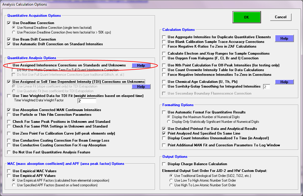
More importantly, as demonstrated above, Probe for EPMA gives the operator an easy way to test the effect of the interference correction on the counting statistics by simply toggling the interference correction on and off. Just to demonstrate, this toggling of the interference correction can be performed with a single mouse click as seen here:

« Last Edit: April 18, 2014, 02:39:12 PM by John Donovan »
The only stupid question is the one not asked!

John Donovan

  • Administrator
  • Emeritus
  • *****
  • Posts: 3304
  • Other duties as assigned...
    • Probe Software
Re: Detection limits and error in the case of peak interference
« Reply #6 on: April 25, 2014, 04:47:59 PM »
OK, I just thought of a way to answer John Spratt's question about including counting statistics for the interference correction in our detection limit calculations.

In the above examples I showed that, in one case the relative percent standard deviation (expressed as %VAR) decreased with the interference correction applied and another sample where the relative percent standard deviation increased with the interference correction applied.

So what we really need is a detection limit calculation which includes the standard deviation of the sample, and in fact we already do. It's the t-test for detection limit from Goldstein, et al. and shown here:


Since this expression is already implemented in Probe for EPMA as seen here:


So all one has to do is check this box in the Calculation Options dialog, and the t-test detection limit will automatically include the change in variance due to the interference correction.

 8)

Here is some sample output using this statistics output option, first without the aggregate intensity feature:

Detection Limit (t-test) in Elemental Weight Percent (Average of Sample):

ELEM:       Ti      Ti      Ti      Ti      Ti
  60ci  .00008  .00004  .00019  .00014  .00009
  80ci  .00013  .00007  .00032  .00022  .00015
  90ci  .00018  .00009  .00044  .00031  .00021
  95ci  .00024  .00012  .00057  .00040  .00028
  99ci  .00039  .00020  .00095  .00066  .00046

and here *with* the aggregate intensity feature:

Detection Limit (t-test) in Elemental Weight Percent (Average of Sample):

ELEM:       Ti      Ti      Ti      Ti      Ti
  60ci  .00008     ---     ---     ---     ---
  80ci  .00012     ---     ---     ---     ---
  90ci  .00017     ---     ---     ---     ---
  95ci  .00022     ---     ---     ---     ---
  99ci  .00037     ---     ---     ---     ---


The "60ci" label refers to 60% confidence interval and the "99ci" refers to 99% confidence interval.
John J. Donovan, Pres. 
(541) 343-3400

"Not Absolutely Certain, Yet Reliable"