Author Topic: Flow Proportional Counter Backflow Gas Regulation  (Read 21295 times)

Brian Joy

  • Professor
  • ****
  • Posts: 296
Re: Flow Proportional Counter Backflow Gas Regulation
« Reply #30 on: November 24, 2018, 09:57:07 AM »
Below is a new plot of GFPC bias as a function of atmospheric pressure with ~22 feet of tubing added to the P-10 exhaust.  I've only had a chance to make a handful of measurements in the past few weeks, but it seems clear that the addition of the tubing makes little or no difference.  The cool-weather regression lines do not include the new measurements.


EDIT 2018-11-28:  I may have made a conclusion based on too little data.  Measurements that I've made during the past few days suggest that bias actually has shifted to lower values (to get a distribution centered at 4 V at a count rate of 5000 s-1).  I'll post a new plot at some point during the winter.
« Last Edit: November 28, 2018, 01:15:25 PM by Brian Joy »
Brian Joy
Queen's University
Kingston, Ontario
JEOL JXA-8230

Ben Buse

  • Professor
  • ****
  • Posts: 498
Re: Flow Proportional Counter Backflow Gas Regulation
« Reply #31 on: November 29, 2018, 09:58:11 AM »
I’ve continued to add data to my plot of GFPC bias versus atmospheric pressure.  Lately we’ve had some larger oscillations in pressure as is typical of the non-summer months.  I’m curious to know if other JEOL users who have gas flow counters arranged in series see the same pattern that I do:  the spectrometer that serves as the P-10 exhaust 1) requires higher counter anode bias and 2) shows a smaller slope on the plot of bias versus pressure than the one into which the P-10 enters.


Hi Brian,

This is really interesting what you've done, I'm hoping to repeat the measurements. I've just taken some measurements today and yes the exhaust spectrometer has a higher voltage. Pressure 997.8 mb, inlet spec 1710, outlet spec 1718

Ben

DavidAdams

  • Professor
  • ****
  • Posts: 57
Re: Flow Proportional Counter Backflow Gas Regulation
« Reply #32 on: December 18, 2018, 07:36:59 AM »
It's very interesting to see these plots! I'm glad I'm not the only one experiencing this.

What are everyone's P-10 pressures set to? The JEOL engineer here has set our 8530F gas pressure to 0.068 MPa. Does anyone know what the maximum pressure specification for the flow counters is?

Thanks!
« Last Edit: December 18, 2018, 09:01:42 AM by DavidAdams »
David Adams
The University of Auckland
Faculty of Science | School of Environment

Ben Buse

  • Professor
  • ****
  • Posts: 498
Re: Flow Proportional Counter Backflow Gas Regulation
« Reply #33 on: January 10, 2019, 06:39:33 AM »
Hi,

What type of curve should you fit to a PHA spectra (bias scan) - e.g. Gaussian, etc. So far split pearson 7 seems to work.

Ben
« Last Edit: January 10, 2019, 08:06:18 AM by Ben Buse »

Brian Joy

  • Professor
  • ****
  • Posts: 296
Re: Flow Proportional Counter Backflow Gas Regulation
« Reply #34 on: January 11, 2019, 05:03:39 PM »
Hi,

What type of curve should you fit to a PHA spectra (bias scan) - e.g. Gaussian, etc. So far split pearson 7 seems to work.

Ben

Hi Ben,

The distribution is usually described as "quasi-Gaussian," with σ < √N, where N is the average number of primary ion pairs produced by an X-ray photon.  Fano (1947, Physical Review 72:26-29) showed that σ = √FN = √FE/ε, where E is the photon energy and ε is the mean ionization energy of the counter gas.  For argon, the "effective" F is usually set at 0.8 and takes into account widening of the distribution due to secondary ionizations produced during avalanching.  See Reed's "Electron Microprobe Analysis," 2nd ed., p. 86-87.

Brian
« Last Edit: January 11, 2019, 07:29:58 PM by Brian Joy »
Brian Joy
Queen's University
Kingston, Ontario
JEOL JXA-8230

Ben Buse

  • Professor
  • ****
  • Posts: 498
Re: Flow Proportional Counter Backflow Gas Regulation
« Reply #35 on: January 22, 2019, 08:19:13 AM »
Here's some initial results

Gas in at Sp3, out at Sp1.


Also shown are the maximum height and the FWHM of the bias scan

« Last Edit: January 22, 2019, 08:23:24 AM by Ben Buse »

Probeman

  • Emeritus
  • *****
  • Posts: 2856
  • Never sleeps...
    • John Donovan
Re: Flow Proportional Counter Backflow Gas Regulation
« Reply #36 on: January 22, 2019, 08:48:43 AM »
Here's a dumb question:  I know that the JEOL gas flow spectrometers are generally(?) connected in series as Ben mentions above (gas in at Sp3, out at Sp1), but I suspect that the Cameca (gas flow) spectrometers are connected in parallel.

From a recent visit to PNNL, I noticed that their P-10 bottle is tiny and yet they claim it lasts around a year. However on the Cameca there are 5(!) bubblers all running at the same time.  So even though we use a full size cylinder, our P-10 cylinder only lasts about 4 to 6 months.

Does anyone know if the Cameca spectrometers can be connected in series like the JEOL?  Are the any pros vs. cons on this question?
john

Edit by John: Edgar Chavez confirms the Cameca WDS spectrometer P-10 gas flow is in parallel.
« Last Edit: January 22, 2019, 11:05:07 AM by Probeman »
The only stupid question is the one not asked!

Karsten Goemann

  • Global Moderator
  • Professor
  • *****
  • Posts: 228
Re: Flow Proportional Counter Backflow Gas Regulation
« Reply #37 on: January 22, 2019, 02:27:02 PM »
Does anyone know if the Cameca spectrometers can be connected in series like the JEOL?  Are the any pros vs. cons on this question?

I don't think doing in series for Cameca is possible as they run at different pressures ("low" pressure similar to the JEOL P10 channels, and "high" pressure for higher kV where JEOL uses Xe). You would need at least two "chains" one low, one high pressure?

That's probably also the reason that the JEOL P10 bottles last that long? Their overall P10 usage would be equivalent to 1 low pressure spectro on a Cameca?

Cheers, Karsten

Probeman

  • Emeritus
  • *****
  • Posts: 2856
  • Never sleeps...
    • John Donovan
Re: Flow Proportional Counter Backflow Gas Regulation
« Reply #38 on: January 22, 2019, 06:47:05 PM »
Does anyone know if the Cameca spectrometers can be connected in series like the JEOL?  Are the any pros vs. cons on this question?

I don't think doing in series for Cameca is possible as they run at different pressures ("low" pressure similar to the JEOL P10 channels, and "high" pressure for higher kV where JEOL uses Xe). You would need at least two "chains" one low, one high pressure?

That's probably also the reason that the JEOL P10 bottles last that long? Their overall P10 usage would be equivalent to 1 low pressure spectro on a Cameca?

Cheers, Karsten

That's a good point. One would need two systems, one for the 1 atm and one for the 2 atm detectors.  But still one would be using (theoretically) half the gas flow for the two high pressure detectors and 1/3 the gas flown for the others.

Based on the bubble rate I don't think the high pressure detectors flow any more gas than the low pressure detectors.  They're both about one bubble per second.
john
The only stupid question is the one not asked!

Mike Matthews

  • Global Moderator
  • Professor
  • *****
  • Posts: 142
Re: Flow Proportional Counter Backflow Gas Regulation
« Reply #39 on: January 23, 2019, 09:58:16 AM »
One benefit of the Cameca parallel plumbing is when you’ve got a leaking counter window it’s really easy to see which spectrometer it’s on.

Probeman

  • Emeritus
  • *****
  • Posts: 2856
  • Never sleeps...
    • John Donovan
Re: Flow Proportional Counter Backflow Gas Regulation
« Reply #40 on: January 23, 2019, 11:04:28 AM »
One benefit of the Cameca parallel plumbing is when you’ve got a leaking counter window it’s really easy to see which spectrometer it’s on.

That is a very good point.

That said, the 2 atm detector windows very rarely leak as they are 1.5 um(?) Be, and on the three 1 atm flow detectors that our instrument has, one can choose door #1, door #2 or door #3!    ;)

https://en.wikipedia.org/wiki/Monty_Hall_problem
The only stupid question is the one not asked!

Mike Matthews

  • Global Moderator
  • Professor
  • *****
  • Posts: 142
Re: Flow Proportional Counter Backflow Gas Regulation
« Reply #41 on: January 24, 2019, 10:24:05 AM »
One benefit of the Cameca parallel plumbing is when you’ve got a leaking counter window it’s really easy to see which spectrometer it’s on.

on the three 1 atm flow detectors that our instrument has, one can choose door #1, door #2 or door #3!    ;)

https://en.wikipedia.org/wiki/Monty_Hall_problem

Hmm, 3 doors and only one is leaking. All you need is three trolls that you’re only allowed to ask one question of and you’ve got a proper riddle.

Probeman

  • Emeritus
  • *****
  • Posts: 2856
  • Never sleeps...
    • John Donovan
Re: Flow Proportional Counter Backflow Gas Regulation
« Reply #42 on: January 24, 2019, 02:34:57 PM »
One benefit of the Cameca parallel plumbing is when you’ve got a leaking counter window it’s really easy to see which spectrometer it’s on.

on the three 1 atm flow detectors that our instrument has, one can choose door #1, door #2 or door #3!    ;)

https://en.wikipedia.org/wiki/Monty_Hall_problem

Hmm, 3 doors and only one is leaking. All you need is three trolls that you’re only allowed to ask one question of and you’ve got a proper riddle.

Hi Mike,
Well seriously, it is an interesting dilemma because it would be nice to see which spectrometer has a leaky detector window.  That said, we haven't had a bad detector window since we added these "soft start" values to our roughing pumps about 5 years ago:

https://probesoftware.com/smf/index.php?topic=120.msg487#msg487

And I sure wouldn't mind if our P-10 gas lasted several times longer!

I'll run it by our instrument engineer and see what he thinks...
The only stupid question is the one not asked!

Brian Joy

  • Professor
  • ****
  • Posts: 296
Re: Flow Proportional Counter Backflow Gas Regulation
« Reply #43 on: February 01, 2019, 08:43:14 AM »
I’ve continued to add to my plot of GFPC anode bias versus atmospheric pressure over the past few months.  It appears that the addition of 22 feet of tubing to the channel 4 exhaust had little or no effect, and this is a little puzzling.  I expected the added tubing to at least reduce the amount of scatter present in the measurements on channel 4, but the magnitude of the scatter appears unchanged.


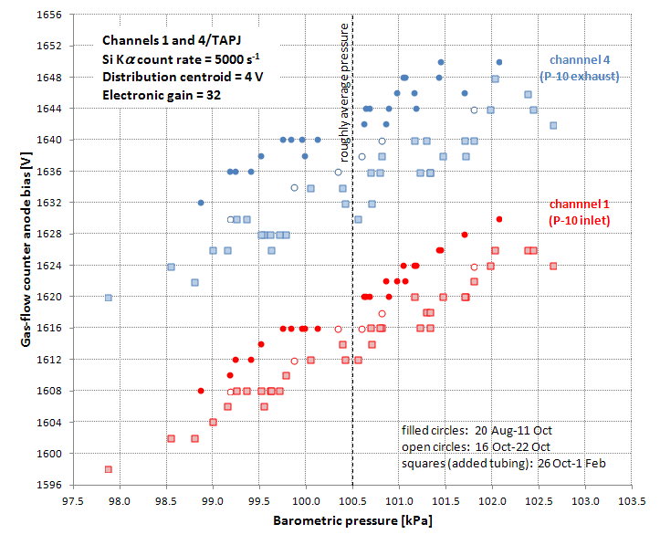
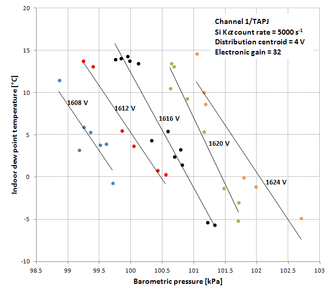
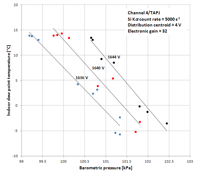
Clearly at least one other independent variable (in addition to atmospheric pressure) is important in order to account for scatter in the plot.  In the following plots, I’ve contoured indoor dew point temperature versus atmospheric pressure for anode bias in 4 V increments.  Although the plots would benefit from some more measurements, it seems clear that water content of the atmosphere affects the anode bias required to keep the distribution centered at 4 V (while maintaining count rate at 5000 s-1), even with the added tubing.  So I’m sticking to my claim that air is actually mixing with P-10 in the gas-flow counters.  On the plot above, as dew point decreases (to as low as ~-5°C in the past month) the anode bias for given atmospheric pressure also decreases.  (In the summer, dew point temperature ranges as high as ~+15°C.)


I’ll keep adding to these plots at least through next summer to see if my results from late last summer are reproducible.  By the way, I’m keeping track of dew point with the Lascar EL-USB-RT thermometer/hygrometer, which displays temperature and dew point in real time and also periodically dumps data to a file.  It can be gotten at Amazon for about $60 U.S.
« Last Edit: February 01, 2019, 08:59:26 AM by Brian Joy »
Brian Joy
Queen's University
Kingston, Ontario
JEOL JXA-8230

dawncruth

  • Professor
  • ****
  • Posts: 76
Re: Flow Proportional Counter Backflow Gas Regulation
« Reply #44 on: August 29, 2019, 10:45:16 AM »
Hey Karsten,
In October 2018 you said:

In any case, probably another reason to put something on the exhaust. I tried filling our bubbler with diffusion pump oil (to avoid the somewhat nasty dibutylphthalate) but it was way too viscous at room T. So now I'm trialling Alcatel 200 rotary pump oil, which seems to have the right sort of viscosity (with bubbler close to half filled 26 nicely shaped bubbles per minute, with P10 pressure regulator set at 16 kPa, flow regulator to around 1.15 ml/minute). From the specs it is hopefully fairly clean and long-term stable ("double distilled hydrocarbon fluid, low backstreaming ... strong oxidation resistance, ... for corrosive applications..."), so I'll see how that goes. It is a double chamber bubbler so even in the case of a detector window failure it shouldn't suck the fluid all the way back into the detectors (in theory, at least...). If anyone has a better idea what to use let me know. I'd still be interested in the back pressure regulator setup even at low altitude such as in our case.

Cheers,
Karsten

What was the outcome of your experiment? I'm going through the same process.
Dawn