I've been continuing to work on developing a method for trace carbon in steel and I am discovering that there's more that I don't know, than I do know!

It's quite interesting how variable these carbon contamination effects are. For example last June I was performing some carbon measurements using the TDI scanning method (replicate x-ray map frames and extrapolation to zero time on a pixel by pixel basis), and found that the carbon behaves much as we would expect as described here:
http://probesoftware.com/smf/index.php?topic=933.msg5990#msg5990However, on some carbon point analyses in the past (2015) shown here:
http://probesoftware.com/smf/index.php?topic=48.0and recent point analyses performed this month, I instead see a downward trend over time as seen here:
These are from a traverse of a heat treated sample displaying every 5th point. Each point is several microns apart so they should not be intersecting any carbon from a previous analysis position. Why would the carbon levels decrease over time? The system is quite clean (we use a 100K cryo trapped system) and the sample was carefully cleaned in ethanol and dried in a 60C oven just prior to being placed in the instrument.
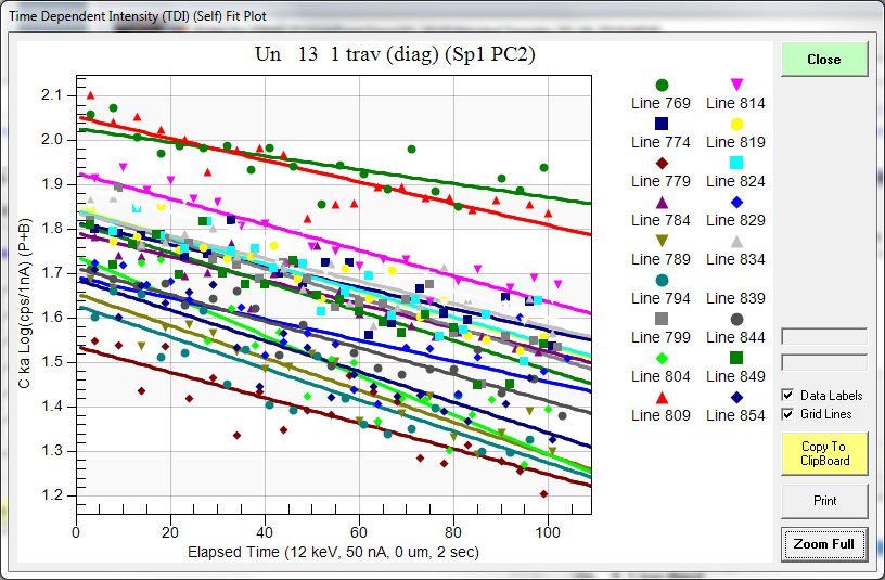
Anyway, if this is of any interest to anyone, I thought I would step through the process of analyzing these samples for trace carbon and share what I have learned about characterizing trace carbon in steel. First off, here are the results for the first 12 data points, without any specialized corrections. That is, merely off-peak and matrix corrected results:
Un 13 1 trav (diag)
TakeOff = 40.0 KiloVolt = 12.0 Beam Current = 50.0 Beam Size = 0
Un 13 1 trav (diag), Results in Elemental Weight Percents
ELEM: C N Al Mo Cr Fe Mn Ni Si V
BGDS: EXP EXP EXP LIN LIN LIN LIN LIN EXP LIN
TIME: 40.00 40.00 80.00 80.00 80.00 20.00 40.00 40.00 80.00 60.00
BEAM: 50.42 50.42 50.42 50.42 50.42 50.42 50.42 50.42 50.42 50.42
ELEM: C N Al Mo Cr Fe Mn Ni Si V SUM
769 1.561 12.073 .012 1.117 4.902 85.393 .309 .126 .858 1.342 107.693
770 1.666 11.584 .016 .989 4.854 86.282 .348 .204 .894 .592 107.430
771 1.018 5.889 .011 1.104 5.087 89.852 .324 .149 .950 1.121 105.506
772 .974 5.972 .020 1.048 5.116 89.821 .358 .175 .965 1.063 105.512
773 1.088 5.141 .016 1.015 5.085 91.173 .360 .095 .993 .661 105.625
774 1.230 6.735 .015 1.032 5.100 88.904 .371 .108 .977 .866 105.339
775 1.316 5.323 .013 1.070 5.165 90.751 .372 .154 .994 1.019 106.177
776 1.054 5.001 .018 1.096 5.233 89.668 .346 .118 .984 1.401 104.920
777 .966 5.065 .014 1.125 5.247 89.899 .330 .075 .976 1.524 105.220
778 1.012 4.642 .012 1.010 5.167 91.519 .371 .146 1.007 .509 105.395
779 .925 4.452 .011 1.057 5.196 91.330 .365 .163 1.023 .472 104.995
780 .942 4.759 .008 1.158 5.237 91.516 .321 .189 1.014 .599 105.743
Pretty awful as one can see. Oh, I guess I should show the background fits for carbon (and nitrogen), so here they are, first for carbon:
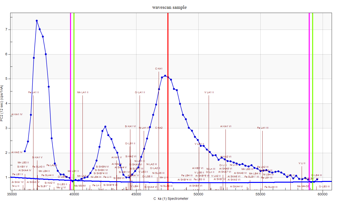
Now we can assume that are not seeing the actual carbon background here. The tails in this region extend a long way, especially when using LDE/PC multi-layer Bragg crystals for these emission lines. But measuring too high a background, would give us *lower* carbon results than we expect, not higher. Either way, the blank correction should take care of it. And here are the results for the nitrogen scan:

So, now let's add in some other corrections that might be useful. Let's start with the TDI correction, which (unfortunately) we would expect to further increase our carbon concentration since we are seeing (for whatever reason!), negative slopes in our carbon TDI plots:
Un 13 1 trav (diag)
TakeOff = 40.0 KiloVolt = 12.0 Beam Current = 50.0 Beam Size = 0
Un 13 1 trav (diag), Results in Elemental Weight Percents
ELEM: C N Al Mo Cr Fe Mn Ni Si V SUM
769 1.687 12.426 .012 1.124 4.905 85.939 .310 .126 .858 1.343 108.731
770 1.825 12.013 .016 1.006 4.864 85.644 .348 .204 .894 .593 107.408
771 1.182 5.907 .011 1.115 5.094 88.742 .324 .149 .950 1.122 104.597
772 1.084 5.959 .020 1.049 5.117 89.920 .358 .175 .965 1.063 105.710
773 1.364 5.181 .016 1.030 5.092 90.421 .360 .095 .993 .662 105.214
774 1.393 6.908 .015 1.048 5.108 88.082 .372 .109 .976 .867 104.879
775 1.570 5.366 .013 1.054 5.170 90.220 .372 .154 .994 1.020 105.933
776 1.311 5.339 .018 1.146 5.242 89.817 .347 .118 .984 1.403 105.725
777 1.086 5.105 .014 1.139 5.248 90.361 .330 .075 .976 1.524 105.858
778 1.272 4.520 .012 1.017 5.165 92.675 .371 .146 1.007 .509 106.695
779 1.070 4.407 .011 1.047 5.200 90.444 .366 .163 1.023 .472 104.204
780 1.110 4.931 .008 1.182 5.242 91.641 .321 .189 1.014 .599 106.237
And sure enough we're seeing a small increase of carbon, for example the first data point goes from 1.56 wt.% to 1.69 wt.%. And the average TDI parameters are here:
TDI%: 15.038 1.388 -.169 .025 ---- -.044 ---- ---- ---- ----
DEV%: 2.7 8.2 3.0 4.5 ---- .3 ---- ---- ---- ----
TDIF: LOG-LIN LOG-LIN LOG-LIN LOG-LIN ---- LOG-LIN ---- ---- ---- ----
TDIT: 102.90 104.42 137.20 137.16 ---- 71.79 ---- ---- ---- ----
TDII: 6.13 2.30 3.40 2.59 ---- 87.2 ---- ---- ---- ----
TDIL: 1.81 .832 1.22 .952 ---- 4.47 ---- ---- ---- ----
So a 15% increase in carbon at the ~1.5% wt.% level. But why are our totals so darn high? Well first of all, we appear to have some "native" carbon on our sample, as a "blank" measurement on pure Fe gives us about 1 wt.% carbon. Interestingly, if we look at the carbon TDI on our blank we see almost no TDI effect:
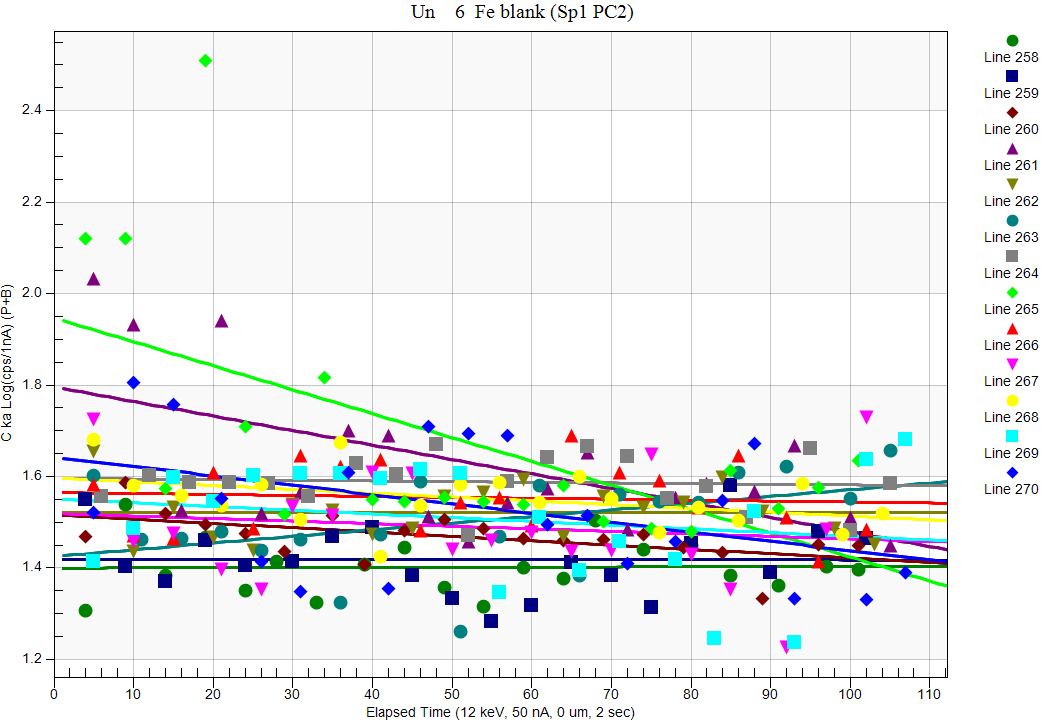
How weird is that? Same instrument, different sample...
Now after the blank correction is applied we now obtain these quant results:
Un 13 1 trav (diag)
TakeOff = 40.0 KiloVolt = 12.0 Beam Current = 50.0 Beam Size = 0
Un 13 1 trav (diag), Results in Elemental Weight Percents
ELEM: C N Al Mo Cr Fe Mn Ni Si V SUM
769 .557 12.112 .012 1.124 4.889 85.662 .309 .126 .859 1.339 106.987
770 .696 11.708 .016 1.006 4.848 85.365 .347 .204 .895 .591 105.675
771 .048 5.751 .011 1.115 5.077 88.448 .323 .149 .951 1.119 102.991
772 -.051 5.802 .020 1.048 5.099 89.625 .357 .175 .966 1.060 104.101
773 .231 5.045 .016 1.030 5.075 90.126 .359 .095 .994 .660 103.631
774 .260 6.727 .015 1.048 5.091 87.793 .370 .108 .977 .865 103.254
775 .439 5.227 .013 1.054 5.153 89.931 .371 .153 .995 1.016 104.352
776 .178 5.199 .018 1.145 5.224 89.525 .346 .118 .985 1.399 104.137
777 -.049 4.971 .014 1.138 5.230 90.067 .329 .074 .977 1.520 104.272
778 .137 4.403 .012 1.016 5.148 92.378 .370 .146 1.008 .508 105.127
779 -.065 4.290 .011 1.046 5.183 90.147 .364 .163 1.024 .471 102.634
780 -.026 4.803 .008 1.181 5.225 91.344 .320 .188 1.015 .597 104.656
Now we are seeing carbon pretty much hovering around zero, but our totals are still pretty bad. What could be going on?
Well I didn't mention this yet, but most of you probably guessed that the standards are carbon coated, but the unknown sample is *not* carbon coated- because, you know, we're trying to analyze for carbon here!
And at 12 keV, the low overvoltage affects the Fe Ka emissions pretty strongly. And I should also mention that this is why we should always utilize standards- because if we normalize to 100% every analysis looks perfectly fine... So let's specify a carbon coat for the standards by checking these boxes in the Analysis Options dialog:

The standards are by default specified as 20 nm of carbon, now how do we specify no coating for our unknown sample? We use the calculation Options dialog as seen here and simply uncheck the Use Unknown Conductive Coating correction for the sample as seen here:

And now we obtain these results, with the TDI, blank and coating corrections:
Un 13 1 trav (diag)
TakeOff = 40.0 KiloVolt = 12.0 Beam Current = 50.0 Beam Size = 0
ELEM: C N Al Mo Cr Fe Mn Ni Si V SUM
769 .548 10.071 .012 1.093 4.714 82.164 .297 .119 .836 1.294 101.147
770 .682 9.734 .015 .978 4.674 81.887 .334 .193 .871 .571 99.940
771 .050 4.766 .011 1.085 4.904 84.977 .311 .141 .925 1.083 98.253
772 -.045 4.809 .019 1.020 4.925 86.107 .344 .166 .940 1.026 99.311
773 .226 4.180 .015 1.002 4.903 86.609 .346 .090 .967 .639 98.978
774 .256 5.578 .015 1.019 4.915 84.323 .357 .103 .951 .837 98.354
775 .427 4.331 .013 1.025 4.979 86.419 .358 .146 .968 .984 99.648
776 .175 4.308 .018 1.114 5.047 86.028 .334 .112 .958 1.354 99.448
777 -.044 4.118 .014 1.108 5.053 86.555 .317 .071 .950 1.471 99.613
778 .136 3.647 .011 .989 4.975 88.794 .357 .139 .980 .491 100.520
779 -.059 3.553 .011 1.018 5.008 86.649 .351 .155 .996 .456 98.137
780 -.021 3.979 .008 1.150 5.048 87.788 .308 .179 .988 .578 100.004
Holy Toledo, that's not looking too bad! Maybe we can actually perform trace carbon analyses after all...


