Author Topic: PictureSnap calibration  (Read 3690 times)

Mike Spilde

  • Post Doc
  • ***
  • Posts: 18
PictureSnap calibration
« on: October 31, 2016, 03:59:52 PM »
Is there a calibration that needs to be done between PictureSnap and the image scan on the JEOL 8200? I notice that when I use Digitize Image in the Automate window to collect an image, there is a slight discrepancy between the size of the digitized image in PFE and what is on the JEOL monitor. The PFE digitized image is somewhat longer in the Y and narrower in the X axis. Then when I use PictureSnap to locate points, they are offset on the image from the actual position on the probe. Specifically, if the points are in the lower half of the image, the PictureSnap points are offset downward from where the real point is on the probe and upward if they are in the upper half of the PictureSnap image, like the image has been stretched vertically. The offset is proportional to the vertical distance from center, so points near the center are fine, but those near the bottom of the PictureSnap image are offset by more than the width of the analysis point that is displayed in PictureSnap and likewise in the upper part of the image.
Thanks,
Mike

Probeman

  • Emeritus
  • *****
  • Posts: 2856
  • Never sleeps...
    • John Donovan
Re: PictureSnap calibration
« Reply #1 on: October 31, 2016, 04:13:57 PM »
Is there a calibration that needs to be done between PictureSnap and the image scan on the JEOL 8200? I notice that when I use Digitize Image in the Automate window to collect an image, there is a slight discrepancy between the size of the digitized image in PFE and what is on the JEOL monitor. The PFE digitized image is somewhat longer in the Y and narrower in the X axis. Then when I use PictureSnap to locate points, they are offset on the image from the actual position on the probe. Specifically, if the points are in the lower half of the image, the PictureSnap points are offset downward from where the real point is on the probe and upward if they are in the upper half of the PictureSnap image, like the image has been stretched vertically. The offset is proportional to the vertical distance from center, so points near the center are fine, but those near the bottom of the PictureSnap image are offset by more than the width of the analysis point that is displayed in PictureSnap and likewise in the upper part of the image.

Hi Mike,
One difference between the image from Digitize Image or the Imaging window and the video image you see on the JEOL monitor, is that the JEOL live image monitor is showing the video scan generator image while the Digitize Image and Imaging windows in PFE utilize the mapping scan generator.  So the different scan generators will produce different images though I'm sure your JEOL service engineer can adjust them to be fairly close. 

I would start by re-calibrating your Digitize Image/Imaging window using the method described here:

http://probesoftware.com/smf/index.php?topic=396.0

It works extremely well and can be calibrated for multiple magnifications and scan rotations.  I think someone is supposed to be writing up a short tutorial on this (Karsten: was that you?).  Anyway, it's not hard so if you read the above topic in the CalcImage board you should be good to go.  The basic idea is to utilize a stage scan to calibrate your beam scan.
john
The only stupid question is the one not asked!

Probeman

  • Emeritus
  • *****
  • Posts: 2856
  • Never sleeps...
    • John Donovan
Re: PictureSnap calibration
« Reply #2 on: November 01, 2016, 04:28:41 PM »
One thing to consider is the image shift. If you are digitizing points using a video image and the previously acquired analog image was acquired with the image shift not exactly zero, the digitized points will be off by that amount.

The other thing to consider is that the analog signal images are very dependent on the acquisition speed due to hysteresis effects in the scanning coils.  So if you want to accurately display the digitized stage points on an analog signal image, be sure to acquire analog signal images using the slowest scan speed and also a fairly high pixel resolution.
john
« Last Edit: November 01, 2016, 11:21:28 PM by Probeman »
The only stupid question is the one not asked!

Probeman

  • Emeritus
  • *****
  • Posts: 2856
  • Never sleeps...
    • John Donovan
Re: PictureSnap calibration
« Reply #3 on: November 02, 2016, 03:35:46 PM »
Let me start by saying that high accuracy metrology on the microprobe isn't easy!

So I ran a number of tests on the imaging calibration and analysis position accuracy and my conclusion is that there is nothing wrong (that I can see) with either the beam scan calibration code, nor the analysis position plotting code.  I will explain my testing methodology below where I utilized the Save To Database button in the Imaging window to save the images and then displayed the analysis positions on the acquired images in the Run | Display, Annotate and Export Analog Signal Image menu dialog, but I also tested several images in PictureSnap and everything looks exactly the same there.

First let's look at an image I acquired with the analysis positions displayed (you'll probably want to click on the embedded images to see them better):


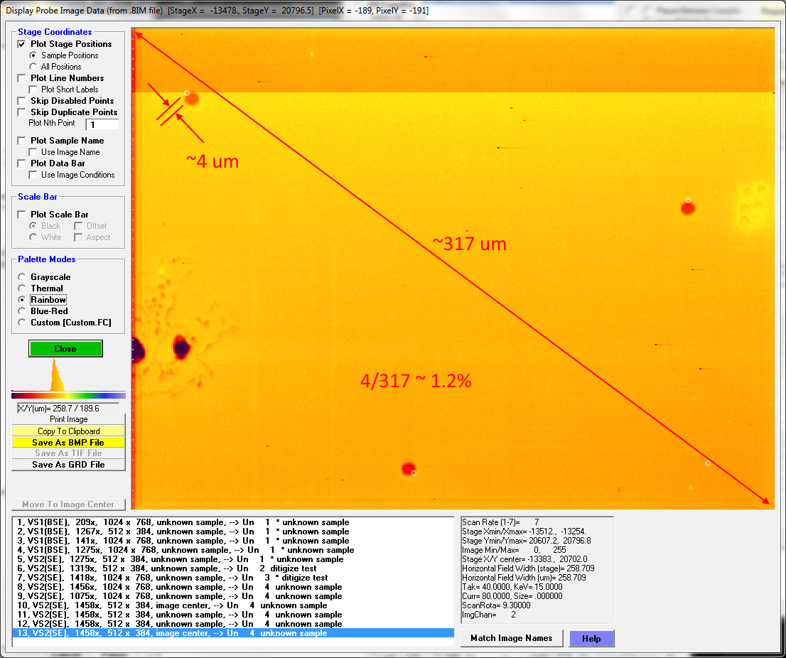
So there is some offset from the beam burn positions, but please note that this image was acquired using my default calibration from ~6 months ago, which could be suspect as we had a complete column rebuild since then, but a larger issue I soon discovered was that I only calibrated up to 1335x and the recent image calibration testing I did was at magnifications a little higher than that. So there is some extrapolation involved. (By the way, I've never had our engineer adjust the scanning coil electronics, and instead have always opted for a software calibration.)

But first let's calculate the relative accuracy of these displayed positions relative to the beam burn positions on the above image.  Using the click and drag feature in the Display, Annotate and Export Analog Signal Image dialog, I found that the image diagonal length is ~317 um and for the upper left analysis point, the distance between the beam burn and the displayed circle is about 4 um, which is an error of about 1.2% relative, or about 2.4% relative based on just the radius.  Since Cameca instruments have a specified accuracy of 3% relative for magnification, that doesn't seem all that awful, but perhaps we can do better.

But first let's look more closely at the same image and see if we can determine whether it's the displayed image or the displayed analysis positions that are in error. The coordinates of the analysis positions are listed here:

Stage (or Beam Deflection) Coordinate Positions:
          X          Y          Z                 X          Y          Z
    4G  -13490.00   20771.00   69.00000     5G  -13289.00   20729.00   69.00000
    6G  -13399.00   20622.00   69.00000     7G  -13281.00   20626.00   69.00000

Starting with the first analysis position (point 4), we have a recorded stage coordinate of -13490 for x and 20771 for y. Here is the mouse cursor captured while sitting on the displayed analysis position for point 4:


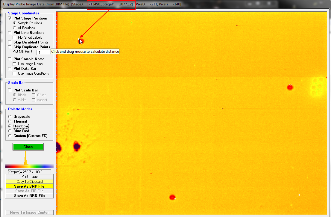
We can see that the displayed analysis position is exactly at the acquired stage coordinates, and in fact it is the image (and beam burn) that is off from the calibrated stage position!  We can do the same for the other two positions and in all cases the displayed analysis position is *exactly* at the acquired stage position, while the beam burn (image) is off in calibration. Here is point 5 (-13289.00   20729.00):


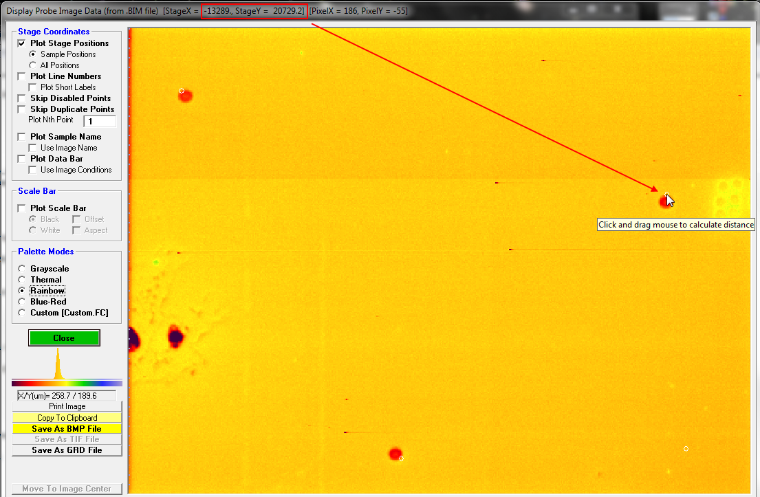
And here is point 6 (-13399.00   20622.00):


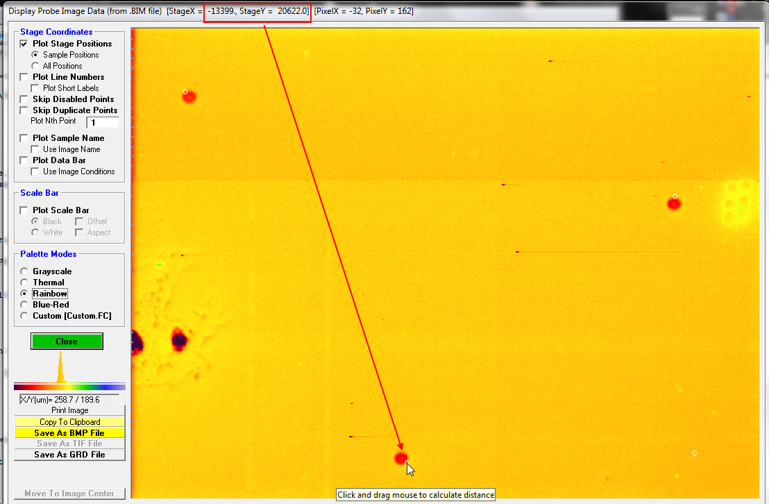
So, to me this means that the software is correctly displaying the stage positions, but the image itself is not exactly calibrated.  In the next post I will continue the discussion of my testing, but please feel free to disagree with me...
« Last Edit: April 12, 2020, 08:02:37 PM by John Donovan »
The only stupid question is the one not asked!

Probeman

  • Emeritus
  • *****
  • Posts: 2856
  • Never sleeps...
    • John Donovan
Re: PictureSnap calibration
« Reply #4 on: November 02, 2016, 03:44:47 PM »
Now, as I mentioned above, my highest mag beam scan calibration was at 1335x, while the image was acquired at 1458x, so I decided to perform an additional calibration using the "@" symbol button in the Imaging window at a higher mag (note that generally I suggest that one should utilize the stage image/beam image calibration method in CalcImage as described in the CalcImage board, as that method will utilize a three point calibration and therefore also calibrate the scan rotation, which as we will see is also very important.

After the two point beam scan calibration at 1456x I started a new probe MDB file (this is very important as the MDB file contains the beam scan calibrations for the images stored in that MDB file, and if you re-open the MDB with the old calibration, that is what you will get) and re-acquired the images and analysis positions and now the Display... Analog Images dialog shows this:


The beam burns in the image are now much closer to the displayed stage positions, but not exactly perfect.  In fact, to me they seem a little rotated. So I adjusted the scan rotation (probably from the column rebuild we recently had) to 8.5 degrees and re-acquired the image (remembering to turn off the scan rotation send by unchecking the little checkbox next to the Start Image button in the Imaging (or Digitize Image) window) and here is what I got with the same analysis positions:


So this image shows about 0.5% relative error in the image (or ~1% relative) in the radius (for point 4, though better for the others). To which I say: good enough for me!

In addition I decided to acquire some slightly lower magnification images just to see the interpolation code in action and here are some images:


Note that this lower mag image above was acquired with the old scan rotation of 9.3 degrees, so if I had re-acquired it at 8.5 degrees it would be even closer.

Bottom line, getting these beam scan calibrations accurate isn't easy, but it is possible.
« Last Edit: April 12, 2020, 08:02:58 PM by John Donovan »
The only stupid question is the one not asked!

Probeman

  • Emeritus
  • *****
  • Posts: 2856
  • Never sleeps...
    • John Donovan
Re: PictureSnap calibration
« Reply #5 on: November 14, 2016, 04:29:54 PM »
I went and did a few low mag beam scan calibrations in PFE today, to check on the calibration accuracy when below 1000x. I only did two point calibrations from the Imaging window, but when plotted up in CalcImage, the fit looks pretty good:


Here are the calibrations for my Sx100:

; Beam scan calibration
ImageInterfaceCalNumberOfBeamCalibrations="9"
ImageInterfaceCalKeV="15,15,15,15,15,15,15,15,15"
ImageInterfaceCalMag="142,206,298,334,405,571,758,1335,1456"
ImageInterfaceCalXMicrons="2621.54,1799.7,1248.7,1118.275,926.9622,659.7579,498.7495,282.546,263.027"
ImageInterfaceCalYMicrons="2001.77,1378.0,957.1,848.4153,705.2865,504.1712,376.3542,207.0935,195.326"
ImageInterfaceCalScanRotation="8.6,8.6,8.6,8.7,8.8,8.9,9.1,9.3,9.3"

When I load a low mag image (~150x) into PictureSnap and double click on various features, the stage drives to within 5 to 8 um or so, which considering the 2600 um width of the image, that amounts to roughly 1/2% accuracy. That I think is about as good as we're going to get given the hysteresis and non-linear lens effects in EPMA instruments.
john
« Last Edit: April 12, 2020, 08:03:13 PM by John Donovan »
The only stupid question is the one not asked!

Paul Carpenter

  • Professor
  • ****
  • Posts: 46
    • Washington University Analytical Facilities
Beam-Stage spatial calibration and low mag image distortion
« Reply #6 on: November 15, 2016, 11:44:01 AM »
All,

Brief summary: At magnification values below ~100X, spherical distortion of the scanning image results in a disagreement between pixel and stage coordinates. Distortion is a function of column and aperture selection and alignment, and stigmation. Calibration of FOV vs. mag at mag above ~100X is otherwise linear, and has negligible error on beam to stage calibration.

Many of us have attempted to perform beam-stage calibration using whereby points selected on the beam-scanned image are used to define the pixels to stage calibration. Several have observed that at low magnification there is a systematic or radial displacement of the image feature from the known position of the stage coordinates of the same feature (i.e., manifest in the digitized point red circle disagreeing with the known digitized position).

My experience is with the Jeol 8200 and all further technical info is based on calibration data I have acquired.

After discussion we agreed that the relation between field of view and magnification is of the form:

log(FOV) = b-intercept + log(mag) * slope

I made FOV measurements using magnification values from 40X to 10000X on a Cu grid. I did this by acquiring SEI digital images using the JEOL digital image photography mode (OS-9 computer, includes scale bar) which confirmed the calibration of the magnification and included a scale bar. These images were loaded into ImageJ and the scale function was used to determine the field of view (FOV) in microns.

The JEOL instruments I am familiar with do not exhibit a change in image mag or other artifacts as you progress through mag ranges. This is confirmed on my instrument by taking digital images and creating an ImageJ stack and animated gif that show smooth change in mag and no offsets (though at lowest mag this is hard to detect if present).

The calibration results from 37 images from 40X to 10000X give values for this equation of

slope -1.00617, intercept 5.02363, R^2 = "1", ie linear

using the Excel linest function to do a least squares fit.

I have attached two plots:
First a plot of the individual FOV measurements and the fit. The error in this fit 100*[(calculated-observed)/observed]
Second, the error in FOV as a function of mag. This error in pixel to stage conversion is largest below ~100X and not representative of behavior at higher mag.

Using 4 calibration values as required by PFE in the ini file, I used 40X, 100X, 400X, and 1000X. Using the least squares fit to these points I get a calibration equation of:

slope -1.00105 intercept 5.01227

The error for this calibration is less than 2 microns at 40X and less than 0.5 micron at the other mag values.

In practice it would be best to calibrate using mag values above 100X but it is evident that placement to better than 2 microns is limited by typical stage reproducibility rather than this calibration process. Also it is important to check your ini file to make sure the Ix/Iy value is 1 as the sgsp used by the JEOL is using square pixels. I have found that there is no need for different x and y calibration values, this was used in PFE prior to using the 4-point FOV and mag values that are used for this calibration equation.

If you have a grid large enough, you should acquire an SEI image at low mag to confirm the following behavior. The electron beam interacts with the objective aperture and is deflected especially at the four diagonal corners of the square/rectangular image. Notice the image exhibits tangential distortion related to the aperture. The grid should also exhibit displacement away from the axial beam center. This means that the conversion or mapping of the pixel to stage coordinates is in error because the image plane is distorted.

If you google "sem image distortion correction", with matlab also in keywords, you will find info on this topic. The solution is to warp the image to project the pixels to their true location relative to the sample. This correction is magnification-dependent and requires reproducible alignment and stigmation to remove any other issues contributing to image distortion. Clearly the aperture used for most probe work should be the aperture used during calibration of the FOV - mag data.

Additional comments. If a given instrument has an accurate magnification calibration, then the FOV - mag data should be applicable to all instruments that have the same geometry; that is, it seems to me that any Jeol microprobe using the largest aperture at 15 kV, should be able to use the FOV values calculated by these fits I have shown. There really is no need for extensive and repeated calibration unless there are alignment problems and different apertures are being used, etc.

This implies the following for the earth science crowd. Using guide net or mosaic imaging for sample mapping, one should avoid using low mag as each image has distortion at the perimeter. I have used ~80X for this purpose and coupled with the 5% overscan used by the JEOL mapping software, followed by stitching using FIJI, the results are very good (ie the 5% overlap which has distorted pixels, is essentially discarded).


Paul Carpenter
Paul Carpenter
Washington University St. Louis

Probeman

  • Emeritus
  • *****
  • Posts: 2856
  • Never sleeps...
    • John Donovan
Re: Beam-Stage spatial calibration and low mag image distortion
« Reply #7 on: November 15, 2016, 02:55:12 PM »
Brief summary: At magnification values below ~100X, spherical distortion of the scanning image results in a disagreement between pixel and stage coordinates. Distortion is a function of column and aperture selection and alignment, and stigmation. Calibration of FOV vs. mag at mag above ~100X is otherwise linear, and has negligible error on beam to stage calibration.

Hi Paul,
Most excellent post!

I did not perform any calibrations below 100x, because the lowest mag on my instrument is ~142x, which is roughly a 2600 um FOV. 

What is the FOV at the lowest JEOL mag?
john
The only stupid question is the one not asked!

Paul Carpenter

  • Professor
  • ****
  • Posts: 46
    • Washington University Analytical Facilities
Re: PictureSnap calibration
« Reply #8 on: November 16, 2016, 09:20:01 AM »
John,
The FOV at 40X is 2560 microns. You can calculate that from the slope and intercept values in my post.
Cheers,
Paul
Paul Carpenter
Washington University St. Louis

Probeman

  • Emeritus
  • *****
  • Posts: 2856
  • Never sleeps...
    • John Donovan
Re: PictureSnap calibration
« Reply #9 on: November 16, 2016, 09:39:31 AM »
John,
The FOV at 40X is 2560 microns. You can calculate that from the slope and intercept values in my post.
Cheers,
Paul

Hi Paul,
OK, cool.  Thanks.

So the FOVs for JEOL and Cameca instruments are roughly the same at their respective lowest magnifications.
The only stupid question is the one not asked!