Author Topic: Digitizing Complex Line Profiles With Varying Spacing  (Read 5620 times)

Ben Buse

  • Professor
  • ****
  • Posts: 499
Digitizing Complex Line Profiles With Varying Spacing
« on: November 04, 2015, 07:23:14 AM »
This is not something that needs fixing but more putting forward the analytical problem - for ideas suggestions.

I'm doing a series of diffusion profiles (carbon in steel multiple samples). Where I want a small spacing near the boundary and an increasing spacing away from the boundary.

I currently do 10 um spacing first 100 um; 70 um spacing next 1000 um and 150 spacing remainder. Because the interface is not orthogonal I use the picture snap to enter the start and end of the line profile sections. Trying to get it perpendicular over 6 mm. When using digitize line profile - entering start and end - you can't click on the picture snip.

Has anyone found a easy way of doing this?

Ben
« Last Edit: November 04, 2015, 07:30:30 AM by John Donovan »

John Donovan

  • Administrator
  • Emeritus
  • *****
  • Posts: 3304
  • Other duties as assigned...
    • Probe Software
Re: Digitizing Complex Line Profiles With Varying Spacing
« Reply #1 on: November 04, 2015, 07:33:11 AM »
This is not something that needs fixing but more putting forward the analytical problem - for ideas suggestions.

I'm doing a series of diffusion profiles (carbon in steel multiple samples). Where I want a small spacing near the boundary and an increasing spacing away from the boundary.

I currently do 10 um spacing first 100 um; 70 um spacing next 1000 um and 150 spacing remainder. Because the interface is not orthogonal I use the picture snap to enter the start and end of the line profile sections. Trying to get it perpendicular over 6 mm. When using digitize line profile - entering start and end - you can't click on the picture snip.

Has anyone found a easy way of doing this?

Ben

Hi Ben,
Why not just do the line traverse in several steps?  Just click the Traverse button for each "spacing section" after positioning on PictureSnap?

Or do you want to position yourself using PictureSnap for both the beginning and end points of each "spacing section"?

If you were running on the Cameca you could simply pop up the Stage app and use PictureSnap from there while in the PFE Linear Traverse dialog, but because JEOL did not make the EIKS DLL multi-threaded you can't run more than one app at a time from the same folder and so running Stage along side PFE won't work.

I guess I could add a PictureSnap button inside the Linear Traverse dialog?
« Last Edit: November 04, 2015, 07:39:18 AM by John Donovan »
John J. Donovan, Pres. 
(541) 343-3400

"Not Absolutely Certain, Yet Reliable"

Ben Buse

  • Professor
  • ****
  • Posts: 499
Re: Digitizing Complex Line Profiles With Varying Spacing
« Reply #2 on: November 04, 2015, 07:39:15 AM »
So I

(1) Set up 10um spacing line using traverse. Read start more to end using stage drive & read end.

(2) Set up 100um spacing line. - I want the begining to be in the same place as the end of line (1) - if I click traverse button to read in start position when at end of line (1) - then I cannot move to the end position using picture snap - as I have to cancel the traverse input.

So what I do instead is click on the end position using picture snap - then click traverse button - read in end position & type in the start position (which I have written down from the last point of line (1).


SORRY - I didn't read the last line of your post - so its a limitation of EIKS communication - good to know reason
« Last Edit: November 04, 2015, 09:31:42 AM by Ben Buse »

John Donovan

  • Administrator
  • Emeritus
  • *****
  • Posts: 3304
  • Other duties as assigned...
    • Probe Software
Re: Digitizing Complex Line Profiles With Varying Spacing
« Reply #3 on: November 04, 2015, 09:32:44 AM »
So I

(1) Set up 10um spacing line using traverse. Read start more to end using stage drive & read end.

(2) Set up 100um spacing line. - I want the begining to be in the same place as the end of line (1) - if I click traverse button to read in start position when at end of line (1) - then I cannot move to the end position using picture snap - as I have to cancel the traverse input.

So what I do instead is click on the end position using picture snap - then click traverse button - read in end position & type in the start position (which I have written down from the last point of line (1).

Is there a better way?

(Sorry I didn't read the last line of your post - so its a limitation of EIKS communication - good to know reason).

Yeah, if you were running on a Cameca SX100/SXFIVE or JEOL 8900/8200/8500 this wouldn't be a problem, but JEOL insisted that we go through their crappy EIKS interface on the new JEOL instruments for all column commands...

So in summary, you can run multiple apps through the JEOL EIKS interface if the apps are in different folders, because then they can each use their own copy of the EIKS DLLs.
« Last Edit: November 04, 2015, 11:25:11 AM by John Donovan »
John J. Donovan, Pres. 
(541) 343-3400

"Not Absolutely Certain, Yet Reliable"

AndrewLocock

  • Professor
  • ****
  • Posts: 104
    • University of Alberta Electron Microprobe Laboratory
Re: Digitizing Complex Line Profiles With Varying Spacing
« Reply #4 on: November 04, 2015, 02:24:59 PM »
I guess I could add a PictureSnap button inside the Linear Traverse dialog?

Yes, please - it would be nice to use the X-ray maps acquired in ProbeImage to set traverses across the previously mapped samples.

In addition, it would be great to distinguish in PictureSnap the points digitized for the current sample.

For example, we acquired stage-scan maps of Al, Mg, Sc in ProbeImage.
I then used Automate and PictureSnap to set individual points on the Sc map as a single sample.
I would like to set different points on the positionally-corresponding Mg map (which covers the same X-Y) area, and either not see the points previously set for Sc, or have them differently color-coded.

Hope that these are possible.

Thanks!
Andrew
« Last Edit: November 04, 2015, 02:38:07 PM by John Donovan »

John Donovan

  • Administrator
  • Emeritus
  • *****
  • Posts: 3304
  • Other duties as assigned...
    • Probe Software
Re: Digitizing Complex Line Profiles With Varying Spacing
« Reply #5 on: November 04, 2015, 02:42:01 PM »
I guess I could add a PictureSnap button inside the Linear Traverse dialog?

Yes, please - it would be nice to use the X-ray maps acquired in ProbeImage to set traverses across the previously mapped samples.

In addition, it would be great to distinguish in PictureSnap the points digitized for the current sample.

For example, we acquired stage-scan maps of Al, Mg, Sc in ProbeImage.
I then used Automate and PictureSnap to set individual points on the Sc map as a single sample.
I would like to set different points on the positionally-corresponding Mg map (which covers the same X-Y) area, and either not see the points previously set for Sc, or have them differently color-coded.

Hope that these are possible.

Thanks!
Andrew

Hi Andrew,
In thinking about it, I don't think I can display PictureSnap from inside the Digitize Traverse dialog because the Digitize Traverse dialog is modal and PictureSnap in non-modal.  But if I added the capability to be able to click the start and end points in PictureSnap to digitize a traverse in addition to the single point digitizing already there would that work?

If I added a menu option in PictureSnap to only display the currently displayed automation sample (in the Automate! window grid), would that do it for you?
john
« Last Edit: November 04, 2015, 02:52:34 PM by John Donovan »
John J. Donovan, Pres. 
(541) 343-3400

"Not Absolutely Certain, Yet Reliable"

AndrewLocock

  • Professor
  • ****
  • Posts: 104
    • University of Alberta Electron Microprobe Laboratory
Re: Digitizing Complex Line Profiles With Varying Spacing
« Reply #6 on: November 04, 2015, 03:12:30 PM »
I guess I could add a PictureSnap button inside the Linear Traverse dialog?

Yes, please - it would be nice to use the X-ray maps acquired in ProbeImage to set traverses across the previously mapped samples.

In addition, it would be great to distinguish in PictureSnap the points digitized for the current sample.

For example, we acquired stage-scan maps of Al, Mg, Sc in ProbeImage.
I then used Automate and PictureSnap to set individual points on the Sc map as a single sample.
I would like to set different points on the positionally-corresponding Mg map (which covers the same X-Y) area, and either not see the points previously set for Sc, or have them differently color-coded.

Hope that these are possible.

Thanks!
Andrew

Hi Andrew,
In thinking about it, I don't think I can display PictureSnap from inside the Digitize Traverse dialog because the Digitize Traverse dialog is modal and PictureSnap in non-modal.  But if I added the capability to be able to click the start and end points in PictureSnap to digitize a traverse in addition to the single point digitizing already there would that work?

If I added a menu option in PictureSnap to only display the currently displayed automation sample (in the Automate! window grid), would that do it for you?
john

If we could put Start and End points of a traverse in PictureSnap, that should work great!
If we could display just the current automation sample in PictureSnap (and then export it as BMP showing such points) - also great!
Many thanks in advance.

Andrew

Ben Buse

  • Professor
  • ****
  • Posts: 499
Re: Digitizing Complex Line Profiles With Varying Spacing
« Reply #7 on: November 05, 2015, 05:27:27 AM »
I'm doing a series of diffusion profiles (carbon in steel multiple samples). Where I want a small spacing near the boundary and an increasing spacing away from the boundary.

Just an update the what I did to tackle this particular problem - was write an excel macro to create the .pos file which I import into PFE and run.

Few details (1) enter start & end of transerve in spreadsheet. (2) Specified no. of points & spacing for 1st section of line, 2nd section of line & 3rd section of line. (3) run macro - uses simple trignometry to calculate all coordinates. (4) copy script into notepad save as .pos in standard pos directory. (5) Load into PFE & run.

Ben

John Donovan

  • Administrator
  • Emeritus
  • *****
  • Posts: 3304
  • Other duties as assigned...
    • Probe Software
Re: Digitizing Complex Line Profiles With Varying Spacing
« Reply #8 on: November 05, 2015, 07:36:22 AM »
I'm doing a series of diffusion profiles (carbon in steel multiple samples). Where I want a small spacing near the boundary and an increasing spacing away from the boundary.

Just an update the what I did to tackle this particular problem - was write an excel macro to create the .pos file which I import into PFE and run.

Few details (1) enter start & end of transerve in spreadsheet. (2) Specified no. of points & spacing for 1st section of line, 2nd section of line & 3rd section of line. (3) run macro - uses simple trignometry to calculate all coordinates. (4) copy script into notepad save as .pos in standard pos directory. (5) Load into PFE & run.

Ben

Sounds good.

Just a note on what I'm doing:  I'm going to add a button to the Digitize Image window so one can import a PrbImg file from Probe Image for use in digitizing complex arrangements of points, traverses or grids directly on x-ray maps.
John J. Donovan, Pres. 
(541) 343-3400

"Not Absolutely Certain, Yet Reliable"

John Donovan

  • Administrator
  • Emeritus
  • *****
  • Posts: 3304
  • Other duties as assigned...
    • Probe Software
Re: Digitizing Complex Line Profiles With Varying Spacing
« Reply #9 on: November 06, 2015, 04:53:38 PM »
Yes, please - it would be nice to use the X-ray maps acquired in ProbeImage to set traverses across the previously mapped samples.

In addition, it would be great to distinguish in PictureSnap the points digitized for the current sample.

For example, we acquired stage-scan maps of Al, Mg, Sc in ProbeImage.
I then used Automate and PictureSnap to set individual points on the Sc map as a single sample.
I would like to set different points on the positionally-corresponding Mg map (which covers the same X-Y) area, and either not see the points previously set for Sc, or have them differently color-coded.

Hope that these are possible.

Thanks!
Andrew

Andrew, I think I've implemented a nice solution, so let me know what you think.

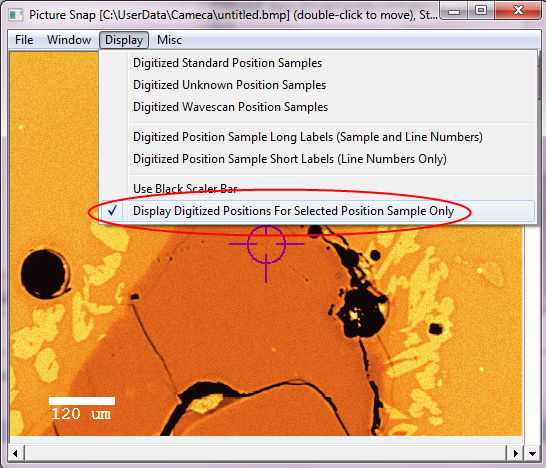
First of all I added menu to PictureSnap that allows one to toggle between all standards, unknown or wavescan digitized positions, or now, only the currently selected position sample in the Automate position sample list as seen here:


But after thinking a bit I decided that adding digitization capability to PictureSnap was going to be quite painful, so what I did instead was add an "Import PrbImg" button to the Digitize Image window as seen here:


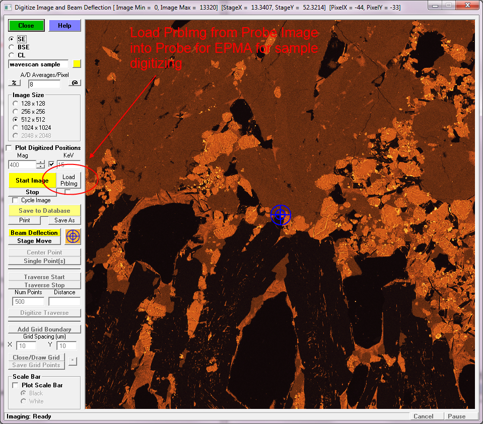
The cool thing is that one can now digitize analysis positions on x-ray maps from Probe Image for points, traverse and polygon grids!

Please try it out and let me know what you think.  The code was interesting to write as I had to handle the fact that the Digitize Image window aspect ratio is defined by the analog beam scan parameters and stage maps from Probe Image might be different.

But that should all be handled automatically for both JEOL and Cameca instruments.

One final comment:  if the PrbImg x-ray map aspect ratio is different than the aspect ratio in the Imaging or Digitize Image window, the software will automatically crop the image to fit.  Therefore if the PrbImg x-ray map is especially short and wide or especially tall and thin, you might want to first crop the approximate area of interest in Probe Image to the approximate aspect ratio in your Imaging or Digitize Image window.
« Last Edit: November 08, 2015, 11:38:05 AM by John Donovan »
John J. Donovan, Pres. 
(541) 343-3400

"Not Absolutely Certain, Yet Reliable"

AndrewLocock

  • Professor
  • ****
  • Posts: 104
    • University of Alberta Electron Microprobe Laboratory
Re: Digitizing Complex Line Profiles With Varying Spacing
« Reply #10 on: November 10, 2015, 04:02:05 PM »
Hi John,
This looks great - I look forward to trying it late this week when my instruments will be available to me (rather than the users).
Thanks very much!
Andrew