Author Topic: Dealing With Magnetic Specimens  (Read 23554 times)

Les Moore

  • Professor
  • ****
  • Posts: 51
Re: Dealing With Magnetic Specimens
« Reply #15 on: December 25, 2017, 05:06:51 AM »
Hi guys,

The interesting issue is why the sample needed to be so big.
If the whole sample is needed to be examined by mapping, then the pixel size will probably need to 50um or so and the deflection will possibly be within the pixel. Also, with this level of deflection you probably wont defocus the oxygen or carbon even if the beam moves within the pixel. Mn, Cr, Co, Ni on a LIF and Si on a TAP would be a different issue.
 
I would imagine the defection will be a function of the centre of mass/magnetic field.
"Mild steel" should not be a hard magnet and should demagnetise easily.  Ask some more questions.

If they want true microanalyses, can you cut the sample up?

Another issue wrt mild steel is the request for carbon and oxygen.  Are you talking to Metallurgists?
In Mild steel, Carbon will be present (barely) in the ferrite, tied up in Fe3C (6.7 wt%) which is present as a grain boundary carbide in low carbon steels ~0.05 wt% C.  This turns into an eutectoid mixture (pearlite) with a local concentration of 0.8wt%. So, the carbon content will be 0.008 in ferrite, 6.7% in Fe3C and a 'bulk' localised analysis of 0.8wt% in pearlite.

Higher cooling rates just make this finer with different transformation mechanisms such as the formation by bainite or martensite; this latter one freezes in the carbon into a metastable phase but you certainly aren't talking about mild steel any more.

The request for oxygen is equally puzzling.  The oxygen, (down to below 20ppm) should all be tied up in oxides.  Oxygen will react with carbon during solidification to form bubbles so it is tied up in strong oxides such as Al2O3 or manganese silicates depending on the steelmaking route.  Again, the oxygen should be 20ppm or 30-40wt% in the oxides which are a few um in size.

Happy to contribute more once more detail available.

Les
PS C maps of large areas tend to just be critiques of the sample preparation process - fingerprints, remnant polishing lubricant, polishing medium, mounting medium etc. 


Probeman

  • Emeritus
  • *****
  • Posts: 2839
  • Never sleeps...
    • John Donovan
Re: Dealing With Magnetic Specimens
« Reply #16 on: December 25, 2017, 10:22:31 AM »
Hi Les,
Good questions.

The large sample is from an engineering company and is a "forensic" sample from a vehicle accident litigation involving multiple fatalities where a modified axle assembly failed.  So the sample cannot be modified as it came from the NTSB, according to the metallurgist I am working with.

They don't care about oxygen, but care very much about carbon in relation to a SS part that was welded on.  I just added oxygen in because I had one spectrometer doing carbon and threw in oxygen since we had doubled up the other spectrometers for other elements. But since the sample was so magnetized, we couldn't use WDS anyway, so all moot.   They don't want maps, they just want point analyses from several regions on the sample near where they performed hardness testing.

We tried using the de-magnetizer (pictured above), several times and could not demagnetize the sample significantly.  I'm hoping someone has a more robust de-magnetizer suggestion for us...

We had good totals using EDS with standards, but oxygen and carbon were either zero or extremely large values due to the large Fe L emission lines they are sitting on.

I agree trace carbon analysis is challenging even with WDS EPMA.
john
The only stupid question is the one not asked!

Les Moore

  • Professor
  • ****
  • Posts: 51
Re: Dealing With Magnetic Specimens
« Reply #17 on: December 29, 2017, 07:12:53 AM »
Ooo errr, serious stuff.

The large sample is from an engineering company and is a "forensic" sample from a vehicle accident litigation involving multiple fatalities where a modified axle assembly failed.  So the sample cannot be modified as it came from the NTSB, according to the metallurgist I am working with.

So let me get this right, have they have welded a stainless steel component to a steel axle?

They don't care about oxygen, but care very much about carbon in relation to a SS part that was welded on. 

If so, why?
Steelmakers try very hard to get the C content in SS as low as possible (unless they are making a martensitic stainless for knife/blade usage and you certainly wouldn't weld that).  They even add strong carbide forming elements such as Ti, V and Nb. This is to avoid CrxCy forming in the heat affected zones or in the weld metal.

In corrosion scenarios, the CrxCy (X & Y depend on the alloy level) forms and locally depletes the areas around the carbides of Cr.  This is called sensitization.  This is quite significant and creates a galvanic cell between the Cr carbides and the Cr depleted regions and corrosion channels in - often called knife edge corrosion.

Background ref:
https://www.corrosionpedia.com/definition/1334/sensitization-stainless-steel
http://www.ssina.com/corrosion/igc.html

A good micrograph of HAZ sensitization:
https://www.hindawi.com/journals/ijc/2011/305793/fig3/
in article:
https://www.hindawi.com/journals/ijc/2011/305793/

Going back to what is going on, if they have welded SS to a high carbon steel axle then you need to map at various scales especially in the heat affected zone of the SS.

I would also be worried about solidification cracking within the weld as the C will significantly change the solidification path and possibly locally form low melting point eutectics that could rip apart.

Note the Vertical axis in the following diagram....
https://www.researchgate.net/profile/Johan_Pilhagen/publication/237660542/figure/fig3/AS:298763013902338@1448242061226/Figure-323-Schaeffler-constitution-diagram-for-stainless-steel-weld-metal-modified-for.png

The C has a scale factor of 30, much higher than any other deliberate alloy.  This can locally change the structure:

eg:
http://products.asminternational.org/fach/content/fach004/graphics/inline/i0017635.jpg

In this case, the situation was similar, a stainless weld on a high carbon steel:
http://products.asminternational.org/fach/data/fullDisplay.do?database=faco&record=642&search=
The problem here was dilution resulting in a drop down the Schaeffler diagram rather than C pickup but you get the idea.

Cheers

Les

My axiom would be to map first and ask questions later.
   

Probeman

  • Emeritus
  • *****
  • Posts: 2839
  • Never sleeps...
    • John Donovan
Re: Dealing With Magnetic Specimens
« Reply #18 on: December 29, 2017, 10:24:37 AM »
So let me get this right, have they have welded a stainless steel component to a steel axle?

Yes. Axle housing I think...

They don't care about oxygen, but care very much about carbon in relation to a SS part that was welded on. 

If so, why?

Steelmakers try very hard to get the C content in SS as low as possible (unless they are making a martensitic stainless for knife/blade usage and you certainly wouldn't weld that).  They even add strong carbide forming elements such as Ti, V and Nb. This is to avoid CrxCy forming in the heat affected zones or in the weld metal.

They are only interested in the carbon in the steel part, not the SS.   Not sure why.

In corrosion scenarios, the CrxCy (X & Y depend on the alloy level) forms and locally depletes the areas around the carbides of Cr.  This is called sensitization.  This is quite significant and creates a galvanic cell between the Cr carbides and the Cr depleted regions and corrosion channels in - often called knife edge corrosion.

Background ref:
https://www.corrosionpedia.com/definition/1334/sensitization-stainless-steel
http://www.ssina.com/corrosion/igc.html

A good micrograph of HAZ sensitization:
https://www.hindawi.com/journals/ijc/2011/305793/fig3/
in article:
https://www.hindawi.com/journals/ijc/2011/305793/

Going back to what is going on, if they have welded SS to a high carbon steel axle then you need to map at various scales especially in the heat affected zone of the SS.

I would also be worried about solidification cracking within the weld as the C will significantly change the solidification path and possibly locally form low melting point eutectics that could rip apart.

This is really interesting stuff. Thanks for posting.  Yes, there is cracking at the weld, which is the concern I think.

My axiom would be to map first and ask questions later.

That would be my preference as well, but they insist they only want a few data points, apparently to keep the costs down. I would have started with WDS mapping of the traces, but the strong magnetism of the sample killed that idea.

Do you have any suggestions for a "professional" grade de-magnetizer?   One of the professors here suggested hooking up a Variac to the demagnetizer and turning it on at zero AC volts and then increasing the AC volts to max and then decreasing it to zero without moving the sample within the demagnetizer.  That's the next thing I'm going to try unless someone has a better idea.
john
« Last Edit: December 29, 2017, 04:10:36 PM by Probeman »
The only stupid question is the one not asked!

Probeman

  • Emeritus
  • *****
  • Posts: 2839
  • Never sleeps...
    • John Donovan
Re: Dealing With Magnetic Specimens
« Reply #19 on: January 20, 2018, 09:06:46 AM »
Do you have any suggestions for a "professional" grade de-magnetizer?   One of the professors here suggested hooking up a Variac to the demagnetizer and turning it on at zero AC volts and then increasing the AC volts to max and then decreasing it to zero without moving the sample within the demagnetizer.  That's the next thing I'm going to try unless someone has a better idea.

OK, I managed to find the old Variac that I knew I used to have somewhere in my garage...  found this pic on the web which is the exact same model as mine (and just about in the same condition!):


brought it to the lab, hooked it up to our de-magnetizer unit, and as my colleague suggested, we set the Variac to zero, placed a strongly magnetized sample inside the de-magnetizer, shown here:


We slowly increased the AC to 120v or so, then slowly decreased the AC and then tested with with a magnetometer.  Result?  Completely demagnetized!

So this is how I will be demagnetizing steel samples from now on.
« Last Edit: April 13, 2020, 10:13:07 PM by John Donovan »
The only stupid question is the one not asked!

Probeman

  • Emeritus
  • *****
  • Posts: 2839
  • Never sleeps...
    • John Donovan
Re: Dealing With Magnetic Specimens
« Reply #20 on: October 10, 2018, 01:53:18 PM »
Warning, this post might be painful to read.   :D

I recently got some large (1.5") metallurgical Fe diffusion samples from a colleague to characterize the diffusion profiles. Unfortunately the samples are quite magnetic and even using the above mentioned demagnetizer did not help. So depending exactly where on the sample I am, the electron beam is significantly deflected away from the WDS x-ray focus location.

Now normally when we have run into samples that cannot be demagnetized, we simply run the analyses using EDS with full standards in Probe for EPMA as this allows us to perform spectral interference corrections, but unfortunately these analyses require characterization of carbon.  And trace carbon by EDS in an Fe, V, Nb alloy is just not going to cut it in my opinion (though I'd be interested to learn otherwise).

Now carbon characterization in a microprobe is hard enough (need to have an uncoated sample and turn off the coating correction the unknowns but leave it on for the standards, use the TDI correction, deal with spectral interferences, etc., etc.), but when one adds severe beam deflection from magnetic samples into the mix, it really is a pain.

For example, when comparing the optical image with the electron image, in one analysis location I'm seeing 49 um of deflection in X and 12 um in Y. In other areas the deflection is just as large but different!  If I simply go ahead and run normal WDS analyses I get ~90% totals because of Bragg defocussing.

So I'm sitting there thinking how the heck am I going to do this?  I could have used the digitized image feature that allows one to acquire a BSE image and then digitize the points right on the image. And since the image would be deflected by the magnetic field just like the spot beam, the beam deflection should all null out.  But for analysis areas larger then the 20 um or so, one is still going to have Bragg defocus issues, and I can't use EDS because they want trace carbon.

So then I wondered about image shift, because the deflection from the magnetic sample is roughly constant over a mm or so. But image shift doesn't really work in spot mode- or does it?

So I switched to scan mode, and looking at the optical image, I adjusted the image shift until the center of the electron image coincided with the optical image. I then manually switched the beam mode to spot, and low and behold, the beam spot showed up and was deflected, even though the image shift controls are now non responsive (as one would expect)!  At least this is the case on my Cameca SX100.

So, then what I did was to utilize a checkbox in PFE that I don't think I've ever used before, but in this situation it is essential, and that is this one here that is normally checked, but I simply unchecked it:


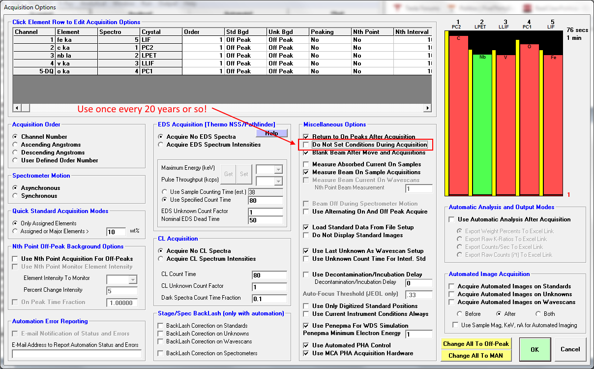
Now the deal is to be sure that the beam and column conditions are exactly as you want them otherwise, and then the software acquires the data with the deflected spot mode beam that hopefully is compensating for the beam deflection caused by the magnetic sample.

And after this, I calculated the results and instead of 90% totals we're doing much better:

n    7 1AV, 3

Un    7 1AV, 3
TakeOff = 40.0  KiloVolt = 15.0  Beam Current = 30.0  Beam Size =    0
(Magnification (analytical) =  40000),        Beam Mode = Analog  Spot
(Magnification (default) =     2245, Magnification (imaging) =    800)
Image Shift (X,Y):                                         .00,    .00
Number of Data Lines:  48             Number of 'Good' Data Lines:  48
First/Last Date-Time: 10/08/2018 05:27:47 PM to 10/08/2018 07:22:20 PM
WARNING- Using Exponential Off-Peak correction for c ka
WARNING- Using Exponential Off-Peak correction for v ka
WARNING- Using Exponential Off-Peak correction for o ka
WARNING- Using Time Dependent Intensity (TDI) Element Correction
WARNING- Using Blank Trace Correction
WARNING- Quantitation is Disabled For o ka, Spectro 4

Average Total Oxygen:         .000     Average Total Weight%:   98.565
Average Calculated Oxygen:    .000     Average Atomic Number:   24.215
Average Excess Oxygen:        .000     Average Atomic Weight:   51.558
Average ZAF Iteration:        2.96     Average Quant Iterate:     3.98

No Sample Coating and/or No Sample Coating Correction

Un    7 1AV, 3, Results in Elemental Weight Percents
 
ELEM:       Fe       C      Nb       V       O
BGDS:      LIN     EXP     LIN     EXP     EXP
TIME:    40.00   40.00   40.00   40.00     ---
BEAM:    30.10   30.10   30.10   30.10     ---

ELEM:       Fe       C      Nb       V     O-D   SUM 
   327    .009   -.019    .000 100.017     --- 100.006
   328    .020   1.103    .000  98.865     ---  99.989
   329    .033    .053   -.002  99.280     ---  99.364
   330    .030    .141   -.006  98.915     ---  99.081
   331    .017    .113    .008  98.143     ---  98.281
   332    .042   -.065   -.011  98.559     ---  98.525
   333    .034   -.045    .016  98.617     ---  98.622
   334    .035    .042    .002  98.318     ---  98.398
   335    .467   4.042   -.011  95.773     --- 100.271
   336  16.404    .070   -.021  82.303     ---  98.756
   337  36.791    .044    .002  62.380     ---  99.217
   338  42.883    .098    .004  55.452     ---  98.437
   339  46.199    .123   -.013  51.821     ---  98.130
   340  48.929    .131   -.004  49.326     ---  98.382
   341  38.853  18.902   -.013  39.861     ---  97.603
   342  51.870    .570    .001  45.361     ---  97.803
   343  54.801    .174   -.006  44.297     ---  99.265
   344  55.998    .147    .007  43.141     ---  99.293
   345  57.067    .168   -.017  41.637     ---  98.855
   346  57.834    .162   -.003  40.631     ---  98.624
   347  59.383    .220    .007  39.498     ---  99.107
   348  59.763    .174    .004  38.741     ---  98.681
   349  61.193    .263   -.012  37.850     ---  99.294
   350  60.820    .499   -.010  36.774     ---  98.083
   351  62.245    .269   -.009  36.380     ---  98.885
   352  62.695    .059    .002  35.104     ---  97.860
   353  61.348   3.872    .012  33.015     ---  98.248
   354  64.923    .270   -.008  34.661     ---  99.846
   355  65.745    .363   -.029  34.140     --- 100.219
   356  65.329    .336    .016  33.287     ---  98.968
   357  66.446    .480    .000  32.807     ---  99.732
   358  66.232    .437   -.009  32.246     ---  98.906
   359  68.073    .282    .000  31.814     --- 100.169
   360  67.658    .306    .013  31.365     ---  99.342
   361  68.051    .358    .004  31.018     ---  99.431
   362  68.374    .390    .013  30.217     ---  98.994
   363  29.768  28.703    .018  14.383     ---  72.872
   364  68.313    .380   -.003  30.694     ---  99.384
   365  71.621    .462    .010  27.391     ---  99.484
   366  71.649    .362   -.025  27.720     ---  99.706
   367  71.290    .327   -.010  27.765     ---  99.372
   368  71.315    .398   -.003  27.864     ---  99.575
   369  71.726    .282   -.007  27.620     ---  99.621
   370  72.036    .304   -.006  27.436     ---  99.770
   371  72.546    .254    .008  26.966     ---  99.774
   372  72.605    .206    .004  26.705     ---  99.519
   373  73.202    .244    .014  26.185     ---  99.644
   374  73.589    .216   -.010  25.956     ---  99.751

AVER:   49.089   1.389   -.002  48.090     ---  98.565
SDEV:   26.548   4.891    .011  26.706     ---   3.846
SERR:    3.832    .706    .002   3.855     ---
%RSD:    54.08  352.14 -597.27   55.53     ---
STDS:      526     506     541     523     ---

STKF:   1.0000   .9635   .9933  1.0000     ---
STCT:  11795.9 74090.3 15247.8 26182.7     ---

UNKF:    .4792   .0050   .0000   .4958     ---
UNCT:   5768.6   398.1     -.2 13218.3     ---
UNBG:     32.2    41.4    18.5    55.1     ---

ZCOR:   1.0343  3.2420  1.1506   .9586     ---
KRAW:    .4890   .0054   .0000   .5048     ---
PKBG:   169.93    5.72     .99  228.95     ---
INT%:     ----    -.02    ----    ----     ---

TDI%:     ----   9.396    ----    ----     ---
DEV%:     ----      .7    ----    ----     ---
TDIF:     ---- LOG-LIN    ----    ----     ---
TDIT:     ----   66.77    ----    ----     ---
TDII:     ----    384.    ----    ----     ---
TDIL:     ----    5.95    ----    ----     ---
BLNK#:    ----      12    ----    ----     ---
BLNKL:    ---- .000000    ----    ----     ---
BLNKV:    ---- .933238    ----    ----     ---

Note also that I utilized the blank correction for carbon by analyzing some points on a portion of the sample that was uncoated pure iron. The analysis above shows a carbon blank of 0.933 wt%, which is then subtracted out during the matrix iteration in Probe for EPMA.  Does this 0.9% represent the native hydrocarbon contamination layer on the sample?  I don't know, but I also noticed that the carbon TDI plots are unusual but I'll post those in another post.
« Last Edit: October 17, 2018, 05:00:26 PM by Probeman »
The only stupid question is the one not asked!

Probeman

  • Emeritus
  • *****
  • Posts: 2839
  • Never sleeps...
    • John Donovan
Re: Dealing With Magnetic Specimens
« Reply #21 on: October 17, 2018, 12:47:17 PM »
These magnetic samples are a real pain since the demagnetizer doesn't seem to do much. To give you a better idea of what I'm dealing with here is an image of the sample. And you can see first of all, the damn thing is a horseshoe magnet!  Actually two horseshoe magnets!


Second, I've marked the magnitude of the magnetic beam deflection, in microns, from the sample (compared to the optical image) in three places on the sample.

By the way, I tried cleaning the surface with ethanol and scrubbing with a Kimwipe, then drying it in a warming oven, but the TDI measurement on an new area on the Fe sample looks pretty much the same as before, and again yields a ~0.9% weight percent carbon blank.


The average TDI correction for the first carbon blank was a 16.9% correction, on the second blank (in this post) it's a 15% TDI correction, probably due to the one point that has a flat slope!

But here's my question: does the direction and/or magnitude of the three beam deflection measurements I made seem to correlate with what one might expect for a horseshoe magnet?

« Last Edit: October 17, 2018, 12:50:39 PM by Probeman »
The only stupid question is the one not asked!

Gian Colombo

  • Post Doc
  • ***
  • Posts: 11
Re: Dealing With Magnetic Specimens
« Reply #22 on: October 19, 2018, 02:21:40 PM »
I've used the image shift/static beam deflection strategy before on my magnetic specimens with pretty good results, at least over the limited distances where the magnetic deflection is uniform.

Recently, I've also had a modicum of success by doing a peak search for each measured element on the unknown magnetic specimen before each quant point and using the shifted peak locations as the reference points for measurement.  I'm assuming this is working because the magnetic beam deflection is causing the spectrometers to be in focus at some new sine theta value without affecting intensity.  Then again, maybe I've just been lucky enough on these specimens that the beam is not far enough off axis to render enough intensity loss that the peak shift is not able to recover.  Sadly, I currently have no way of including an automated peak search before each acquisition point during my quant routines, so I'm doing it manually as needed....ugh.

Even if you could automate it, having to wait for a peak search routine to complete could negatively impact the carbon quant since you'd have to account for contamination buildup as the beam dwells during the peak search.  C'est la vie.

Probeman

  • Emeritus
  • *****
  • Posts: 2839
  • Never sleeps...
    • John Donovan
Re: Dealing With Magnetic Specimens
« Reply #23 on: October 20, 2018, 09:19:37 AM »
Even if you could automate it, having to wait for a peak search routine to complete could negatively impact the carbon quant since you'd have to account for contamination buildup as the beam dwells during the peak search.  C'est la vie.

Indeed!   Or as I sometimes say: "there are many more ways to be wrong than right!"    :)

The problem for me is that the user wants these analyses placed extremely accurately on specific sample locations, but since the magnetic deflection varies slightly over distances of even a few hundred microns, getting the beam exactly where it should be is painful.

I can often get good totals in many places but in some places the beam deflects to outside the Bragg focus and then I know I'm not analyzing the spot I hoped I would be analyzing.  So it's re-align the image shift and try again, and then of course the filament blows and then the P-10 gas low tank warning alarm alerts me.

Perhaps I should say: "There are many more ways to be dead than alive!" 

I'm leaving it until Monday!   >:(
The only stupid question is the one not asked!

Probe321

  • Professor
  • ****
  • Posts: 33
Re: Dealing With Magnetic Specimens
« Reply #24 on: October 29, 2018, 07:33:22 AM »
I encounter magnetism all the time especially with ferrous based alloys and some nickel alloys.  I stress to users to degauss  their sample before examination in the SEM or microprobe.  Been called in to assist users with imaging issues and once I learn what is being examined is an alloy, I have them degauss the sample and usually problems go away.  If not look at the ground path the sample mounting media may have pulled away from the sample giving a marginal ground path.

IT learned the Vertiy degausser did not erase hard drives, but it works for large magnetic samples that don't fit into the small degausser.  Metallographic sample prep can trigger magnetism in a sample,  prime examples of this is cold worked (polished) 304 stainless steel and high chromium white cast iron. Once in awhile the sample holders may be slightly magnetic, which also effects imaging/analysis, but it does not happen very often.

And finally it may not be your sample, it may be some previous sample(s) left some debris in the chamber.  After looking at numerous (a few years worth) of corrosion coupons the service engineer discovered rust particles on the pole piece and after cleaning the imaging issue was resolved.
« Last Edit: October 29, 2018, 09:03:25 AM by John Donovan »

Probeman

  • Emeritus
  • *****
  • Posts: 2839
  • Never sleeps...
    • John Donovan
Re: Dealing With Magnetic Specimens
« Reply #25 on: October 29, 2018, 01:41:29 PM »
Hi Keith,
The imaging isn't affected when the sample is not loaded, so we're pretty sure there's no magnetic particles on the objective lens. But that's a good thing to keep in mind.

The demagnetizer we're using can handle the complete shuttle for the Cameca EPMA which we utilize with a Variac transformer to be most effective:

https://probesoftware.com/smf/index.php?topic=354.msg6656#msg6656

Interestingly, some samples just don't seem to demagnetize very well.  Even worse is that some samples demagnetize fine, but as soon as the electron beam is applied in the instrument, they start visibly drifting (based on the electron image). Furthermore this image drift is perfectly correlated with the time the electron beam is actually unblanked and impacting the sample.

So it appears that the sample is not being affected merely by the magnetic field created by the objective lens. The sample is completely conductive and grounded to the holder using two large pieces of copper tape.  No image drift effect is seen when the electron beam is on the sample holder, but rather only for certain (very rare) materials.  In other words, as soon as we unblank the beam, the image starts drifting, and if we blank the beam and wait a minute of two, and then unblank the beam again, we observe the image drift starting again exactly where we last blanked the beam. The absorbed current is stable and does not change from the time the beam is unblanked.

It is very hard to understand how an electron beam at nA levels of current could induce a magnetic field in a material.  We ran this by one of electron physicists here at UofO and they cannot come up with any explanation for this, so maybe there's a Nobel Prize in it for someone who figures it out!   :D
The only stupid question is the one not asked!

Probe321

  • Professor
  • ****
  • Posts: 33
Re: Dealing With Magnetic Specimens
« Reply #26 on: October 31, 2018, 09:54:13 AM »
We get drifting samples once an awhile also.  Usually it is a ground path issue of some type which can be a challenge to find. 

Probeman

  • Emeritus
  • *****
  • Posts: 2839
  • Never sleeps...
    • John Donovan
Re: Dealing With Magnetic Specimens
« Reply #27 on: October 31, 2018, 10:03:23 AM »
We get drifting samples once an awhile also.  Usually it is a ground path issue of some type which can be a challenge to find.

I know, right.  That's  usually what is going on when one sees this, but it doesn't seem to be the case here. But we'll try again!
The only stupid question is the one not asked!

DavidAdams

  • Professor
  • ****
  • Posts: 57
Re: Dealing With Magnetic Specimens
« Reply #28 on: November 01, 2018, 05:19:24 AM »
Have you tried cooling the samples down to LN2 temperatures and trying the demagnetizing when the samples are cooled?
David Adams
The University of Auckland
Faculty of Science | School of Environment

Probe321

  • Professor
  • ****
  • Posts: 33
Re: Dealing With Magnetic Specimens
« Reply #29 on: November 01, 2018, 10:46:48 AM »
If this is the failure "modified axle assemble" I would suggest not cooling to LN2 temperatures.  It is possible you could change the microstructure of the sample, which maybe crucial to case. The LN2 temperature could force uncompleted metallurgical transformations to completion.  Why back in the good old days, when I did tool steels for a living an LN2 quench forced all retained austenite to convert to martensite the desired microstructure.  Retained Austenite is unstable and when it converts to martensite there is a volume change which can result in cracks forming in the part.

I would suggest checking with the university machine shop (or a local shop) and see if they have a large degausser.

If this is not the "modified axle assemble" it is worth a try though according to the Adams Magnetic Products when you return to room temperature the magnetic field returns that is for magnets anyway, nothing about ferrous magnets.

One question I have is how did the part get magnetized?