Author Topic: Check on image orthogonality  (Read 2975 times)

John Donovan

  • Administrator
  • Emeritus
  • *****
  • Posts: 3276
  • Other duties as assigned...
    • Probe Software
Check on image orthogonality
« on: June 07, 2018, 10:40:39 AM »
V. 1.5.7 of PictureSnapApp now also checks that the stage calibration is close to orthogonal. That is, are square objects in the image actually square in stage units?  Right now, we're only warning the user if the stage calibration is off by more than 10%, but we could tighten that up if necessary.

How could this occur?  Well in a complicated sample the user might select a spot on the instrument stage and thinks it corresponds to a specific object in the image, but they could be wrong.  In these cases the software will pop up this message:


The most obvious way to see this is in the current FOV display which is the floating blue square (or rectangle depending on the specified aspect ratio of your imaging system).  Here is an example of a 1:1 aspect ratio imaging configuration where the x axis stage calibration is off by more than 10%:


One can actually see the distortion in the current FOV display.  Once the stage calibration is corrected, the current FOV display looks much more orthogonal:


Of course if your specified aspect ratio (in the Stage Configuration menu dialog) is actually, say, 4:3 (as it is on my Cameca instrument), then one should expect to see a rectangular FOV display as seen here:


By the way, we also added the stage tilt warning and this FOV orthogonality warning to the PictureSnap feature in Probe for EPMA, so update PFE and PSA and you will enjoy these new features.
« Last Edit: April 13, 2020, 09:09:32 AM by John Donovan »
John J. Donovan, Pres. 
(541) 343-3400

"Not Absolutely Certain, Yet Reliable"

John Donovan

  • Administrator
  • Emeritus
  • *****
  • Posts: 3276
  • Other duties as assigned...
    • Probe Software
Re: Check on image orthogonality
« Reply #1 on: June 20, 2018, 12:39:39 PM »
I made the warning for image calibration orthogonality a bit more strict by setting it from 10% to 8% as seen here:


Note that this error usually comes from the user mistakenly thinking they are on a particular feature, when they are actually on a different feature, particularly for complex fine grained samples where there aren't obvious places to utilize as calibration points.  But it can also occur from images that have non-orthogonality from being tilted during the scanning process.  Here is an example of an image where the stage calibration is significantly off:


Because the wrong calibration position/pixel was selected.  Here it is again after the properly corresponding position/pixel was selected:


Note also the new Load ACQ File for Calibration button in the images above.  This can be useful for when you have images taken with the same sample, but under different conditions. For example, a pair of images, one plane polarized and another crossed polarized.  In other words, one calibrates the first image using two or three points as desired, and then for the corresponding image one simply loads the ACQ file from the first image calibration.  And even if the images don't line up exactly, the calibration will probably be quite close and can just be "touched up" for ultimate accuracy.
« Last Edit: April 13, 2020, 08:43:31 AM by John Donovan »
John J. Donovan, Pres. 
(541) 343-3400

"Not Absolutely Certain, Yet Reliable"

Probeman

  • Emeritus
  • *****
  • Posts: 2838
  • Never sleeps...
    • John Donovan
Re: Check on image orthogonality
« Reply #2 on: June 25, 2018, 03:47:38 PM »
On the issue of calibration accuracy and orthogonality: I was working with a student today on the probe and after we loaded his samples into the instrument and looked at them a bit I realized we should have scanned them so we could use PictureSnapApp to navigate them.  But the student said, no worries, he has images he took with his cell phone, so OK, we'll use those.

But right away we noticed that although he had indicated the "up" direction on his samples, which we had used to load them in the sample holder, his photos were pretty rotated with respect to the samples in the instrument, around 20 degrees rotation.

But we went ahead and did the two point calibration, and the calibration accuracy error was large, as expected (around 30-40%), but we then did a third calibration point to deal with that.  So now we can navigate the sample just fine, but the calibration accuracy really didn't change that much. It went from around 40% to 30%.  And even more telling, the current FOV rectangle didn't have the expected aspect ratio for this instrument.

But again, the PictureSnapApp sample navigation is working fine.  Then it occurred to me, DOH!, that on a sample which is rotated with respect to the image, the FOV should not be drawn orthogonally, but instead, should be drawn rotated!  That is, because the image is rotated, the FOV (and sub images for that matter) should be rotated too!

Then I realized (DOH!, DOH!) that this is why the calibration accuracy was so bad.  We're simply calculating ABS((xdistance - ydistance) / xdistance).   That is why the FOV has the wrong aspect ratio on an image that is rotated with respect to the sample!  What we really need to do is to calculate the stage positions for the rotated FOV!

Or one can simply rotate the image until it matches the sample in the instrument (of course it probably would be easier to load the darn sample in the same orientation as the image to begin with!).  Here is an example with the sample loaded in the instrument and rotated about 20 or 30 degrees to the image:


As one can see, the aspect ratio which should be 1.333 or 4:3, is not at all right.  Also the calculated orthogonal accuracy is 46% which is way high, but completely to be expected in a rotated image  Then we loaded in a copy of the image which the student then rotated on his phone, and then we re-calibrated the image:


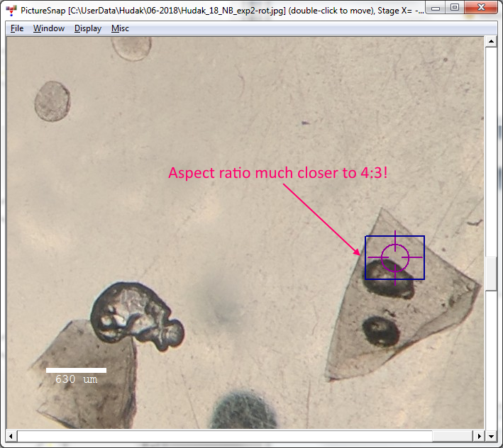
Now one can see that the FOV aspect ratio is much closer to 4:3.  And the calibration accuracy is 1.47%.  Much better!

Bottom line:

1. None of this applies to samples which cannot be rotated. For example, petrographics slides.

2. None of this matters if one only needs to navigate the sample. The stage location of points is always correct. But the displayed FOV (blue rectangle) aspect ratio, may appear distorted depending on the degree of rotation from the sample to the image.

3. If one is using FOV annotations or sub images from the Image Locator feature, then yes, one should rotate the image, or better still, just be sure to load the sample in the same (or close to) the orientation of the image.

4. Donovan is going to have to take a closer look at the issue of rotated images (and the displayed FOV graphic and FOV annotations). Calculating and drawing the rotated FOVs is easy once one knows the degree of rotation of the sample. In fact, with three calibration points this rotation falls nicely out of the calculated rotation matrix, but with two points...  he will have to think about that a bit.  Another difficulty will be with rendering the sub images in the image locator feature properly rotated.
« Last Edit: April 12, 2020, 10:09:08 PM by John Donovan »
The only stupid question is the one not asked!

John Donovan

  • Administrator
  • Emeritus
  • *****
  • Posts: 3276
  • Other duties as assigned...
    • Probe Software
Re: Check on image orthogonality
« Reply #3 on: June 28, 2018, 04:39:41 PM »
The latest version of PictureSnapApp now calculates and displays the degree of rotation between the sample and the image:


That reminds us that if ones sample is mounted rotated in the instrument at a significant angle to the image being calibrated (such as the example in the previous post above), to be perfectly accurate we really ought to be rotating the current FOV graphic (and FOV annotations and sub images for that matter!).  Point annotations and the current position graphic are not affected since they are round graphical objects.

Since that will take a bit of work to implement we went ahead and modified the code to at least save the calculated stage to image rotation value for new FOV annotations and sub images.

This will allow one to see these FOVs properly rotated once we get this new code implemented. So we suggest that you all update your PictureSnapApp (using the Help menu as usual) to be able to utilize this new information when it becomes available for download.

Again, if you mount your sample in a similar orientation to the calibrated image, you won't noticed any problems.  As mentioned previously, this is only an issue when the image is significantly rotated relative to the sample and you want the FOV graphics to be represented exactly correct on the image.
« Last Edit: April 12, 2020, 09:57:44 PM by John Donovan »
John J. Donovan, Pres. 
(541) 343-3400

"Not Absolutely Certain, Yet Reliable"

Probeman

  • Emeritus
  • *****
  • Posts: 2838
  • Never sleeps...
    • John Donovan
Re: Check on image orthogonality
« Reply #4 on: July 26, 2018, 09:56:13 AM »
Julie Chouinard and I came up with an alternative for utilizing PictureSnapApp on our FEI Quanta.

A visiting professor wanted to use our FEI Quanta SEM to document their 25 mm round epoxy sample mount with a number of framboids. Her goal being to then go to a SIMS instrument to do the isotope work, but the sample was gold coated. Therefore our usual optical methods for scanning the sample didn't work very well.

Then Julie said, let's use the "montage" feature in our Thermo Pathfinder software on the Quanta to make a mosaic image of the sample area of interest using the BSE signal, which easily penetrates the gold coating.

This worked great, eventually. Though since this was the first time we've used the image automation in Thermo Pathfinder since installing it a few weeks ago, I tested the imaging on a small area of the sample holder and was surprised to see that although the images were acquired fine, the "Montage" feature didn't assemble the images correctly in the mosaic. The images were put together in exactly the opposite order from what they should be!

So I said, OK I must have got the stage polarities wrong in the Thermo AutomationClient.exe app, where one specifies the instrument hardware connections.  But when I opened the app up, the "increasing X values" was to set to "East" and the "increasing Y values" was set to "North".   So unless my dyslexia is really kicking up, this should be correct for an FEI SEM instrument with a "cartesian" oriented stage. Correct? So, I changed it to increasing X to "West" and increasing Y to "South" and it all worked fine then. WTF?

Anyway, then we opened the "montage" BSE scan from Thermo Pathfinder into PictureSnapApp and then found our calibration points and clicked Calibrate as usual, and we were surprised to see how orthogonal and unrotated the image calibration was, as seen here:


That is until I realized that of course it's orthogonal, since we acquired the mosaic image in the SEM and then calibrated the image in the SEM.  The reason being that image is only likely to be rotated when mounting a round sample in a sample holder, and only non-orthogonal when using a camera which could have various distortions due to the camera angle relative to the sample when snapping the image.

Anyway, this is another way in which one can utilize PictureSnapApp for finding areas of interest on one instrument (in this case an SEM), and then moving the PSA annotation and image set to another instrument (in this case a SIMS). Since the text input mode of PictureSnapApp is free, she can download the software in Wisconsin and calibrate her BSE montage on their SIMS, and easily re-locate her grains.
« Last Edit: April 12, 2020, 08:11:30 PM by John Donovan »
The only stupid question is the one not asked!

Probeman

  • Emeritus
  • *****
  • Posts: 2838
  • Never sleeps...
    • John Donovan
Re: Check on image orthogonality
« Reply #5 on: October 26, 2018, 09:47:29 AM »
This is an example of "spurious accuracy" in PictureSnap. That is to say, accuracy too good to be true, or at the very least, we got lucky!

A student had mounted their samples in the sample holder when we realized it would be a good idea to have a picture of them to make navigating her samples easier. So we decided to just use our document camera and take a picture of the entire holder.

I placed the sample holder under the camera and while watching the live image in the camera software, rotated the sample holder until it looked fairly orthogonal to my eye at least. We snapped the picture, cropped it and opened it into the PictureSnap feature in Probe for EPMA (we could instead have used PictureSnapApp but didn't this time). Here is the screen shot with the calibration points displayed:


One trick we did, is to utilize some scribed lines, I made on the sample holder a while back, to obtain the X/Y stage coordinates, and then use the optical camera on the EPMA to specify the Z height on the actual samples. This way, we are aligned to the sample holder in X/Y and calibrated to the samples in Z.   8)

So where is the "spurious accuracy"?  Well here is a screen shot of the calibration window, and remember, we just plopped the sample holder down on the counter and rotated it for approximate orthogonality by eye:


0.07% rotation?  Now that is lucky!
« Last Edit: October 26, 2018, 10:03:45 AM by Probeman »
The only stupid question is the one not asked!