Author Topic: How do you manage standard position files in PFE (and standards in general)?  (Read 6261 times)

Karsten Goemann

  • Global Moderator
  • Professor
  • *****
  • Posts: 227
All,

I wanted to ask how people are organising their standard position files in PFE. From what I can see so far I either have to
(1) put our standards always in the same position in the different holders to be able to use a single position file,
(2) use fiducials to recoordinate the standard positions if I put the mount in a different position, or
(3) create separate position files for each standard mount for each possible (or at least frequently used) position in the holders.

What works best will probably depend a lot on how the standards are mounted and organised in general, what sort of instrument and sample holders you've got, what sort of work you do...

At Uni of Tasmania we have many different standard "blocks" (all 1" diameter) in use for different purposes. We have a Cameca SX100 that can only accommodate up to 6 1" mounts at a time and it is not really feasible to put the standard blocks always in the same position, although most of our different holders have 2 1" mount positions in the middle, so 2 position files for those could cover many occasions. So I guess option (3) would be a bit of work to set up, but probably the most efficient in daily use afterwards. At this stage I'm still using Cameca PeakSight to load block layouts and drive to standards, as there I can assign a particular mount to a particular position in the holder with a couple of clicks. This is not fiducial corrected, so the positions vary somewhat depending on rotation etc during mounting, but often I just want to quickly drive to the approximate standard position and then quickly adjust the position manually.

When I came to UTAS I didn't bring any standards, and in the past standards in the lab had been mounted in 1" diameter epoxy mounts whenever new standards were acquired. The Smithsonian silicates/oxides had been spread across 3 mounts, we have separate mounts for apatites, carbonates, silicate glasses, REE phosphates, geochronology purposes, completely separate mounts for some metals like Au, Ag, Te,... an Astimex block with 54 standards on it where we mainly only use some sulphides and oxides... So at the moment we already need 7 different blocks to calibrate a hydrous silicate program, 8 different blocks for primary and secondary standards for a monazite run and so forth. 99.9% of our work is Earth Sci related.

So far we've continued using that system but many of those blocks are decades old and needed replacement, so we've now started to mount new standards individually in 3mm diameter mounts. We can put 37 of them in a 1" wheel, and our machine shop has also made a custom holder for us that occupies the space of two 1" diameter positions which can hold 102 standards. That way we hope we will have 100 standards mounted permanently in the instrument that cover 99.9% of the work, are removed from user interference, and can be refurbished individually.

But it is a lot of work to set up (and possibly maintain) and from talking to a few other people I suspect that all sorts of systems are in use, so I'd be interested in your opinions, solutions etc.

Cheers,

Karsten


« Last Edit: September 01, 2013, 10:40:08 AM by John Donovan »

cschwandt

  • Graduate
  • **
  • Posts: 5
    • Director of Industrial Services & Senior Research Scientist
We use option 2.

I just have a cautionary reminder regarding individually polished standards that are inserted into a group block.  As the edge of the block determines the plane of the standards as they are presented to the spectrometers, when you have multiply prepared standards it is extremely difficult to insure that each individual standard was prepared in normal fashion such that the sleeve was truly parallel to the sleeve axis during preparation.  So, all standards must be prepared with robust automated equipment without any "manual by hand" finishing steps, otherwise although you may have a wonderful preparation surface, the standard surface will not be parallel to the block surface and thus the take-off plane.  Slight inclination of the standards can lead to a lot headaches with sorting out what is happening (been down this road in two different institutions, on a SX100 and a JXA-8200). 

So, although there are other issues of different hardness, etc.; you might consider mounting materials with similar hardness and preparing as single blocks.

John Donovan

  • Administrator
  • Emeritus
  • *****
  • Posts: 3274
  • Other duties as assigned...
    • Probe Software
I'll describe the practice in our lab, but I would just first say that there is no perfect method.

We mount our standard materials in a 25 mm diameter machined acrylic block about 1 cm thick, and drilled with 3/32" (~0.1") holes in a pattern that produces 35 positions. See attached pdfs at the end of this post.

Each through hole in the block is filled with epoxy (most of the time using "Petropoxy") and the standard material is introduced from the back and allowed to sink to the front, using a thin wire to dislodge adhering bubbles.

Very tedious work, but the advantage is that when the block sets up, it is a single solid piece with no cracks or crevices to retain oil or other contaminants. True, the overall diameter will shrink somewhat, especially when using Petropoxy, but when it comes time to repolish or re-coat, it couldn't be simpler. Just 20 to 30 seconds on the colloidial silica lap, clean with some ethanol, oven dry and re-coat. Yes, every two years or so we need to go back to diamond to remove beam damage and flatten everything, but as long as you have sufficient standard material in each hole, the block should last for generations.

This is good for us because we re-coat our metal blocks several times a year to keep surface oxidation to a minimum, which is not generally feasible for individually mounted stds. Maybe it's just me, but the problem I've seen with individually mounted standards in blocks, is that they never seem to get enough re-polishing/re-cleaning in actual laboratory day to day conditions.

In addition to these standard mount fabrication/re-furbishing methods, we tried hard to design each 35 standard block to include pretty much everything we'd need into one or possibly two blocks. A few times a year we run across a run that requires 3 mounts and we just deal with it with the usual fun and games. I've attached a map of two of our mounts, one for volcanic glasses and minerals and another for one of the big labs here that does a lot of selenide nano-laminate thin films. We give up some flexibility, but it makes it practical to keep the std mounts in tip top shape because polishing and cleaning is so easy (e.g, no dis-assembly/re-assembly).

If we run into a new large project we create similar mounts, but with maybe some epoxy filled but otherwise empty holes that can always be drilled out later for filling (or refilling as the case may be).

Along with this we scribe a triangle on each standard mount to enable the re-locating of three fiducial marks (made with a very sharp and thin scribe by twirling it between the fingers which usually produces a nice deep round hole in the acrylic typically less than 200 um in size) for calibrating the mount for rotation and translation in PFE when importing the .POS files.  Each std block its own POS file. In fact, we use a separate file for each mount in each of the six possible positions (up to six POS files per std mount).

This isn't as hard as it sounds- once you calibrate the fiducials and standard locations in one std block position, say position 3, you can move that mount to another position and re-locate the fiducials for the new mount location, say position 4. Yes, you have to move some distance to get to the new fiducials, but once they have been confirmed and the new standard locations calculated from the three fiducials, you just save them to a new file name with that position number in the file name as seen here:


After that, it's a simple process to load, maintain and re-save, as necessary, each position file. Sometimes if I only need one or two standards from a 2nd block, I load only the standard mount with the majority of the required standards using the fiducial transformation, and then just manually digitize the extra standard or two. Mostly just to keep the standard list from getting too long in the Automate! window.

John J. Donovan, Pres. 
(541) 343-3400

"Not Absolutely Certain, Yet Reliable"

John Donovan

  • Administrator
  • Emeritus
  • *****
  • Posts: 3274
  • Other duties as assigned...
    • Probe Software
I recently added more buttons for importing digitized positions from an off-line digitizing optical microscope.

The old import feature for .LEP files was buried in the Output menu so I moved it to the Automate! window and also added another button for .DCD files which are generated by the digitizing stage offered through Microbeam Services in Australia. See here:

http://probesoftware.com/smf/index.php?topic=42.msg1852#msg1852

This additional button was suggested by Karsten Goemann in Hobart for his Sx100 because he has the digitizing optical microscope from Microbeam Services, but the odd thing is that the optical microscope stage coordinate system seems to be "anti-cartesian", that is, similar to JEOL in that the x/y min (0,0) is in the upper right corner. See this discussion also:

http://probesoftware.com/smf/index.php?topic=101.msg506#msg506

So right now because the Y optical axis is inverted (as is normal for a petrographic microscope), and because the stage is "anti-cartesian", I have to flip only the X stage coordinates during the import, and all is well.

However, it appears that the Microbeam Services digitizing stage only supports the use of two reference coordinates. If they supported three reference (or fiducial) marks, it would be easy to handle X/Y scaling *and* sample rotation automatically.

Does anyone know if this digitizing software can be modified to support three fiducials. Karsten's suggestion is to use the first sample position as a third fiducial reference, but I guess we should find out first if it already can...  also does the off-line digitizing software always output microns?

Time for an email to Graham I guess...
« Last Edit: November 02, 2014, 10:53:59 AM by John Donovan »
John J. Donovan, Pres. 
(541) 343-3400

"Not Absolutely Certain, Yet Reliable"

Probeman

  • Emeritus
  • *****
  • Posts: 2833
  • Never sleeps...
    • John Donovan
Does anyone have an example of a .lep stage position file generated from a Leica light microscope digitizing stage?

I seem to have misplaced mine.
john
The only stupid question is the one not asked!

John Donovan

  • Administrator
  • Emeritus
  • *****
  • Posts: 3274
  • Other duties as assigned...
    • Probe Software
POS File Format
« Reply #5 on: December 14, 2020, 09:44:29 AM »
For everyone's convenience here is the POS file format documentation from the Probe for EPMA reference manual, for the calibration and transformation of digitized sample positions relative to three reference or "fiducial" locations on the sample.

But it should emphasized that this fiducial transformation technique can be utilized on samples of any size or shape (not just 25mm standard mounts). In other words one doesn't require actual scribed marks on the sample, instead one can utilize any three features visible in the scanned image and which can be located on the sample once it is in the instrument. For example, cracks, corners, bubbles, mineral grains, any small features that can be easily and precisely relocated in the image and on the sample when it is mounted in the instrument.
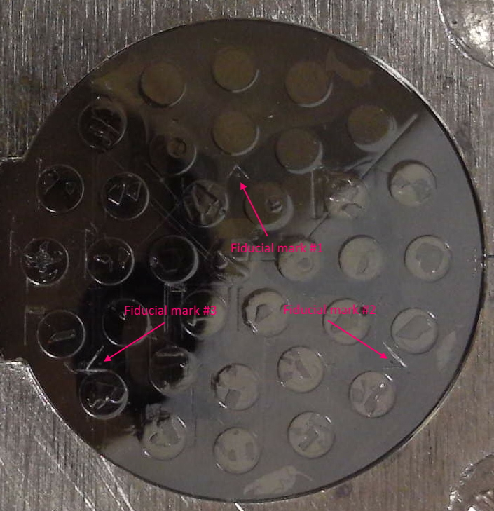


Fiducial Marks
The program will ask the user whether the imported coordinates should be transformed using a fiducial based matrix transformation. The fiducial positions on the standard or unknown sample mount should generally be laid out in an easy to re-locate pattern. Generally it is preferred to place the fiducials marks in the corners of a scribed (or partially scribed- corners only) triangle on the mount surface as shown here :


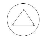
The fiducial marks should be deep enough to withstand repeated re-polishing but small enough to be precise for re-location of the digitized coordinates.

A sample import file of two unknown samples and corresponding positions is shown here. Note that a new standard, unknown or wavescan sample is created automatically by the program during the acquisition process, whenever the sample number changes (for standards), or if the sample name changes (for unknowns or wavescans).

Special note: there are three varieties of formats (type = 1 or type = 2 or type = 3) used in position import and export files. The format of the position import and export file is specified by the PositionImportExportFileType parameter in the PROBEWIN.INI file. If the parameter is not specified in the INI file then the default of type = 1 is used.

The first format is the original import/export format (type = 1) and contains the fields shown in the example below without the autofocus flag and analytical setup number fields shown in parentheses at the end of the position lines.

The second format is a newer import/export format (type = 2) which contains two additional integer fields and an additional string field for each position lines. These additional integer fields are used for an auto focus flag and an analytical setup number. The analytical setup number can be used by Probe for EPMA to specify which previously saved sample setup is to be used when acquiring data for the position sample. Note that all positions in a single position sample must use the same setup number. If more than one setup number is specified within a position sample, the program will use the last analytical setup specified. If the setup number specified is not available in the current Probe for EPMA run, then the program will base the automated acquisition on the last unknown sample.  The autofocus flag is used to define a "digitized" autofocus (if supported by the hardware interface) for each position. If this autofocus flag is zero, then no autofocus is attempted, if the flag is -1 or 1 then an autofocus will be attempted at that position. The adjustment from the auto-focus will be applied to all positions in that position sample.

The additional string field is used to specify a file setup name that can be used for automated designation of a file setup from an existing Probe for EPMA data file.

The importing positions with a pre-defined file setups, analytical setup numbers (and autofocus flag) are useful when digitizing position samples off-line on an optical microscope using program STAGE. However, it is important when digitizing off-line to ensure that the setup number specified during the digitizing process will eventually correspond to the correct setup number created in the Probe for EPMA run in which the digitized position samples will be automatically acquired. Also that the specified file setup data file exists and is updated with valid standardization data.

       0.0, 0.0, 0.0, 0.0
       0.0, 0.0, 0.0, 0.0
       0.0, 0.0, 0.0, 0.0
       2,     1,     "metallic phase #1", 15.234, 18.12, 10.873, 1.0, 1, (1, 4, "")
       2,     1,     "metallic phase #1", 15.547, 18.43, 10.873, 1.0, 1, (0, 4, "")
       2,     1,     "metallic phase #1", 15.698, 18.56, 10.873, 1.0, 1, (0, 4, "")
       2,     2,     "Si3N4 ceramic matrix",15.747, 18.34, 10.873, 1.0, 1, (1, 7, "")
       2,     2,     "Si3N4 ceramic matrix",15.747, 18.34, 10.873, 1.0, 1, (0, 7, "")
       2,     2,     "Si3N4 ceramic matrix",15.747, 18.34, 10.873, 1.0, 1, (0, 7, "")

The format of these standard, unknown or wavescan position import files (the above example contains two unknown position samples with three positions each) is described below. Note that the first three lines are always used to define the coordinates of the 3 physical fiducial marks used for transformation of pre-digitized standard mounts. All parameters are comma, space or tab delimited.

Following the first 3 lines which define the x, y, z, coordinates for the three fiducial marks (used for transformation of pre-digitized standard mounts), each following position line has the following format (the fourth column is not utilized at this time) :

 - the first column contains the sample type (1 = standard, 2 = unknown, 3 = wavescan)

 - the second column contains the sample number, which for standards is the standard number for a standard as defined in the STANDARD.MDB database. For unknowns and wavescans it is an arbitrary number that is ignored.

 - the third column is the sample name, which is optional for standard position samples and must be enclosed in double quotes

 - the fourth, fifth, sixth and seventh columns contains the x, y and z coordinate positions (seventh column is not utilized at this time).

 - the eighth column value is the grain number, which is used for automatically blanking the beam between successive points if different from the preceding point

- the ninth column value (only if PositionImportExportFileType = 2 or greater) is the autofocus flag, which is used for automatically performing an auto focus for each position. Specifically the third autofocus flag option (1= every sample, 2=every point, 3=digitized, 4=interval).

- the tenth column value (only if PositionImportExportFileType = 2 or greater) is the analytical setup number, which is used for automatically loading a previously created sample setup in a Probe for EPMA data file. If the specified analytical setup number is not found, the program will load a sample setup based on the last unknown sample in the run.

- the eleventh column value (only if PositionImportExportFileType = 3) is the analytical file setup name. If the specified file setup name is not found, an error is generated.

Note that standard coordinates can be imported in any order and all positions of a single standard will be appended to a single standard sample automatically. However, if a standard position sample already exists, the program will ask if the user wants to overwrite the existing standard coordinate data, so generally it is a good idea to group all coordinates for a single standard contiguously.

If no fiducial transformation of the imported positions is required, simply click "No" when asked whether to perform the fiducial transformation.

For unknown and wavescan positions these fiducial positions may be used for transformation of sample positions digitized on an optical microscope equipped with a digitizing stage using a different coordinate system than the microprobe stage. All linear transformations in scale, rotation and translation are handled. Although the use of three fiducial coordinates means that the procedure is capable of a three dimensional transformation (using x, y and z), the z coordinate transformation may be ignored, if desired by the user, for unknown or wavescan position transforms.
John J. Donovan, Pres. 
(541) 343-3400

"Not Absolutely Certain, Yet Reliable"

Mike Matthews

  • Global Moderator
  • Professor
  • *****
  • Posts: 142
Being able to reference to the fiducial marks is brilliant but I’d like to propose the benefits of arranging the 3 marks in an ‘L’ shape rather than a triangle. For the triangle arrangement you can't unambiguously orientate the sample without additional information whereas with the ‘L’ configuration any user can look at the sample and know which way round it should be.

John Donovan

  • Administrator
  • Emeritus
  • *****
  • Posts: 3274
  • Other duties as assigned...
    • Probe Software
Being able to reference to the fiducial marks is brilliant but I’d like to propose the benefits of arranging the 3 marks in an ‘L’ shape rather than a triangle. For the triangle arrangement you can't unambiguously orientate the sample without additional information whereas with the ‘L’ configuration any user can look at the sample and know which way round it should be.

Hi Mike,
I think this is actually an excellent idea.

It's hard to see in my previous post, but we do scribe a small "+" sign on the right side of the mount (because, you know, Cartesian...) to help orient the mount, but yeah, it's ideal to have a more obvious aid to the proper mounting orientation.

The reason I choose an equilateral triangle originally is that it gives equal accuracy weighting to both the X and Y axes in the math transformation (the longer the X/Y distance between the fiducials, the better the accuracy), but that's a small effect really.
« Last Edit: December 15, 2020, 04:08:27 PM by John Donovan »
John J. Donovan, Pres. 
(541) 343-3400

"Not Absolutely Certain, Yet Reliable"