Author Topic: Quant Analysis of Carbon Using MAN backgrounds  (Read 17749 times)

BenjaminWade

  • Professor
  • ****
  • Posts: 199
Re: Quant Analysis of Carbon Using MAN backgrounds
« Reply #15 on: October 10, 2017, 08:55:34 PM »
Hi all
Just necroing an old post. A user has come to me wanting to measure C in scapolite, which can contain up to ~4.5wt% C as an end-member. One can calculate it, but they want to try to measure it directly.

I have a PC2 xtal, but no anticontaminator. My standards are currently carbon coated and I am reticent to repolish and recoat my standard block in something like Al. I guess my question is do you think I will be pushing the proverbial uphill, or if the C is in decent concentration (wt% values) I may be able to get some numbers out of it despite no anticontaminator and my carbon coated standards...?

I will probably give it a go anyway using MAN/TDI and see how the numbers compare to the calculated...

Cheers

Probeman

  • Emeritus
  • *****
  • Posts: 2830
  • Never sleeps...
    • John Donovan
Re: Quant Analysis of Carbon Using MAN backgrounds
« Reply #16 on: October 10, 2017, 10:10:38 PM »
Hi Ben,
That is a good amount of carbon, so this shouldn't be too difficult.

No need to strip the carbon coat off your standards.  You can specify a different coat for your unknown and your carbon standard in PFE. 

As you can see from previous posts in this thread I've tested measuring carbon in pure Fe using a graphite standard for carbon, MAN backgrounds and a TDI correction for carbon contamination.

The benefit of using graphite as a carbon standard is that the carbon coat on the graphite standard doesn't affect the standard intensity (pure carbon is pure carbon). And one can specify no carbon coat for your unknown.  Of course if you aren't using a graphite standard for carbon, you could instead just strip the carbon coating off your carbon standard (whatever it is), and coat the carbon standard along with the unknown.

But if the unknown is an insulator you'll have to deal with that.  I suggest a thin metal coating. There is a post here on using Ag for coating insulating samples for carbon analysis:

http://probesoftware.com/smf/index.php?topic=48.msg959#msg959

I ended up using a carbon coated graphite standard, and put 15 nm of evaporated Ag on my unknown, which seemed to work well.   Remember to perform a TDI correction on both the unknown and the carbon standard as the thermal conductivity affects the carbon contamination rate.

Then there is the issue of peak shape for carbon Ka...   Maybe for scapolite you should use a pure siderite (FeCO3) standard as your carbon standard (by assuming carbon concentration by stocihiometry) and coating both the carbon standard and unknown with 15 nm of Ag.   You might want to do some wavescans to see how the peak shapes look on your unknown and standard.

I've never tried measuring carbon in a silicate, so I'm interested to hear what you find.
john
The only stupid question is the one not asked!

BenjaminWade

  • Professor
  • ****
  • Posts: 199
Re: Quant Analysis of Carbon Using MAN backgrounds
« Reply #17 on: October 11, 2017, 04:55:08 PM »
Hi John
Excellent, thanks for the tips.

I have some NMNH R2460 Siderite, and some NMNH R6600 Meionite (Carbon end member of scapolite) mounted in a separate block. I might coat them in C, do some wavescans/measurements on them, then polish/plasma clean/recoat them in Ag at the same time as unknowns to see roughly how much it attenuates my C counts. I guess I will probably still end up using the graphite as the C standard though, will have to see. When I have some wavescans/data I will post it.

Couple more questions...do you think 15nm of Ag is overkill? Seems like a lot. Also as per your previous work, I guess I should use 10kV or so to max my C counts?

Cheers

Probeman

  • Emeritus
  • *****
  • Posts: 2830
  • Never sleeps...
    • John Donovan
Re: Quant Analysis of Carbon Using MAN backgrounds
« Reply #18 on: October 11, 2017, 05:20:19 PM »
Hi John
Excellent, thanks for the tips.

I have some NMNH R2460 Siderite, and some NMNH R6600 Meionite (Carbon end member of scapolite) mounted in a separate block. I might coat them in C, do some wavescans/measurements on them, then polish/plasma clean/recoat them in Ag at the same time as unknowns to see roughly how much it attenuates my C counts. I guess I will probably still end up using the graphite as the C standard though, will have to see. When I have some wavescans/data I will post it.

Couple more questions...do you think 15nm of Ag is overkill? Seems like a lot. Also as per your previous work, I guess I should use 10kV or so to max my C counts?

Cheers

Will be very interesting to see.  Hopefully you can run a silicate with the scapolite that contains no carbon as a "blank".

Yes, a 15 nm coating might be overkill. 10 keV would be good unless you need high sensitivity Fe measurements.
john
The only stupid question is the one not asked!

BenjaminWade

  • Professor
  • ****
  • Posts: 199
Re: Quant Analysis of Carbon Using MAN backgrounds
« Reply #19 on: October 11, 2017, 05:28:16 PM »
Hmm might be difficult finding a silicate that contains similar major element composition as her scapolite. She might have some albite/plag in her samples which I guess will be somewhat similar containing Si/Al/Ca/Na. I will give it a go as well then. I am hoping that the C in her scapolite isn't so low that it will be too much of an issue...

Yes...well what I didn't mention is that the analysis is further complicated by the fact she wants to run F as well, which I like to do on my PC0 which of course is on the same xtal changer as PC2. So we have run some spots last night at normal 15kV with a full element suite including F on PC0. Totals coming out around 98%, of which I am hoping the remainder is CO2+/-H2O. So the plan is to now setup for C, and rerun as close to the analysed spots as possible with the Ag coat, then using the option in PfE combine the selected samples into new samples so the C goes through all the correct matrix corrections. And its all going to work beautifully and perfectly....

Probeman

  • Emeritus
  • *****
  • Posts: 2830
  • Never sleeps...
    • John Donovan
Re: Quant Analysis of Carbon Using MAN backgrounds
« Reply #20 on: October 11, 2017, 06:23:48 PM »
I know it's not quite as good as PC0, but running F Ka on TAP works pretty well especially if you have a large TAP crystal...  then you wouldn't have to combine samples.
john
The only stupid question is the one not asked!

BenjaminWade

  • Professor
  • ****
  • Posts: 199
Re: Quant Analysis of Carbon Using MAN backgrounds
« Reply #21 on: October 11, 2017, 06:32:45 PM »
Yes I did think about it, but I stuck with the PC0 as the F content is quite low, usually less than 500ppm or so. So thought I might be better off with the higher count rate on PC0 and less interferences? In hindsight I guess I should have probably tried it out anyway.

BenjaminWade

  • Professor
  • ****
  • Posts: 199
Re: Quant Analysis of Carbon Using MAN backgrounds
« Reply #22 on: October 19, 2017, 04:43:38 PM »
Hi John and all
Not sure if it’s of any interest, but just thought I would post some of my failures in the last week trying to measure C in scapolite on our SXFive without any form of anticontamination…
Firstly after doing some separate measurements for F we decided that there was little to no F in the scapolite we were looking at, so could ditch F from the package and run C with the rest of the elements to get around the combined analyses problem


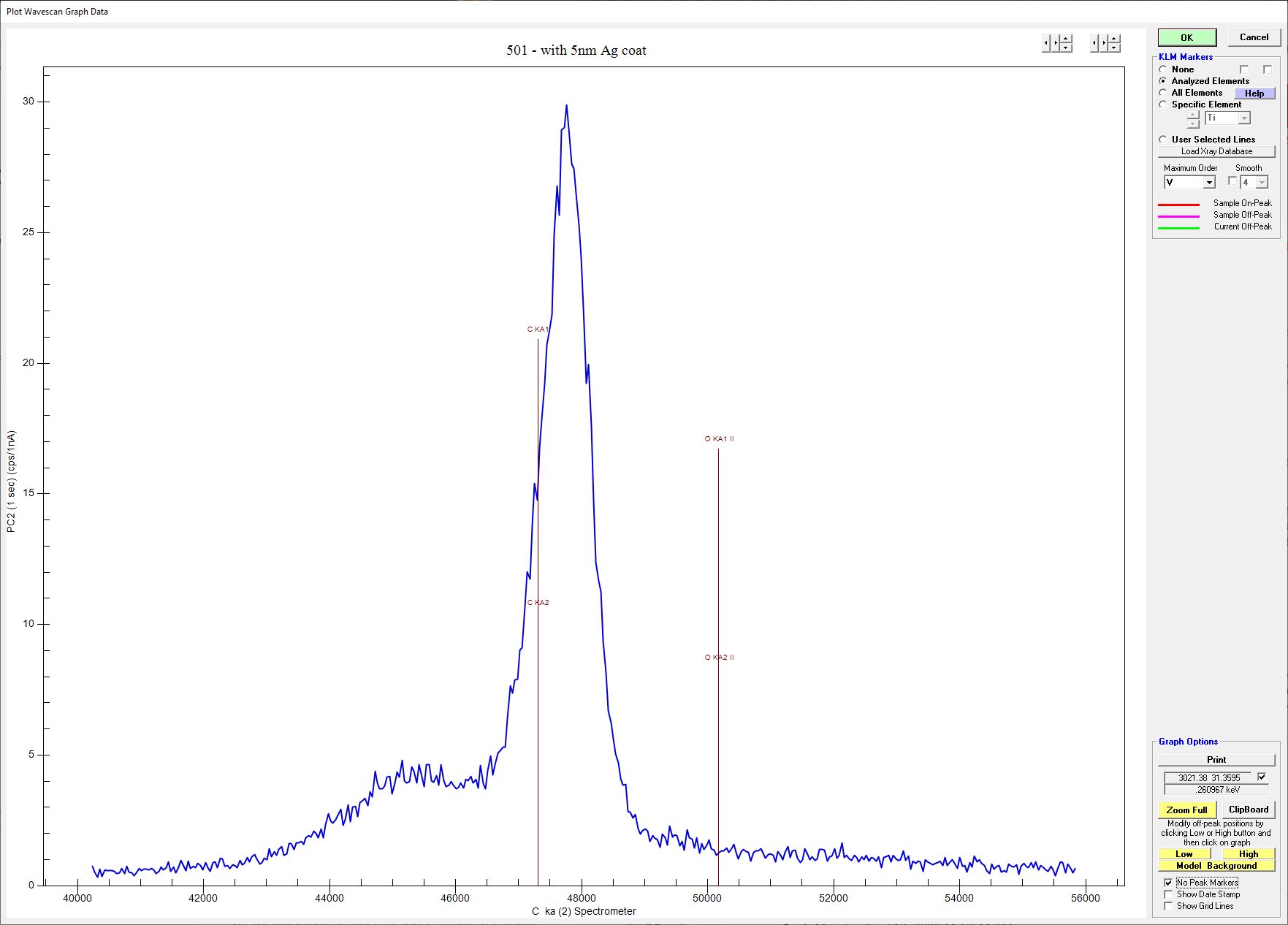
In regards to the coating, I tried both 5 and 10nm of Ag coat.  I get ~1.5 times the counts with a 5nm coat on my scapolite NMNH standard (see wavescans below – ignore the fact that my PC2 xtal is wayyyy out of alignment, that major peak is Oxygen, the carbon peak is the small broader hump to the left of it).


The 5nm seemed to work fine with regards to negating charging so I ended up going with that. To get around having to use coating corrections between standards and unknowns, I ended up finding an older Astimex mineral mount laying around so polished the carbon coat off and coated it in Ag at the same time as the unknowns and NMNH scapolite mount.  Despite me thinking I polished the life out of the samples, getting the samples to the coater quickly and keeping it all under vacuum, I had real problems with C still being measured in minerals that should have none.  Wavescan below shows C peak in standard 501 albite.


Some of my measured C in standards are probably interferences, as seen in MAN fit diagram below for C. I am sure some of it is residual carbon coat/adsorbed carbon to the sample surface, which I guess isn’t unexpected.  If I concentrate on the lower Z end where scapolite will plot (mean Z ~11.6), I can refine the fit to something OK but am not left with many data points (refined MAN fit plot below).  I am hoping that these standards left perhaps don’t have as much residual carbon on their surface and this correlation is real and mostly due to mean Z.  Using the MAN vs traditional, I get ~10% higher carbon values on unknowns so perhaps there is still some other extraneous C contribution.


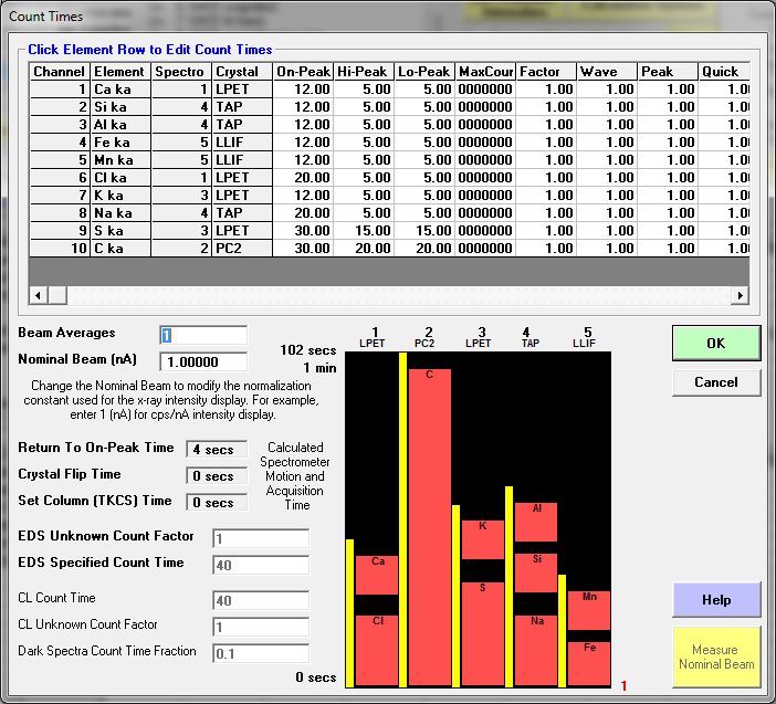
Despite this I ended up running a standards and unknowns at 10kV/35nA/10um defocussed beam.  Both standards and unknowns had TDI enabled. Standards were collected with traditional background methods, and unknowns both with and without MAN for comparison.  TDI plots on unknowns were variable, some spots showing C increase which might be expected, some showing no correlation at all (attached images).


I ended up using NMNH R6600 Scapolite as my Carbon standard for the unknowns.  I tried pure graphite, calcite, dolomite, and all give me extremely high C measurements when treating NMNH R6600 Scapolite as an “unknown” (reported CO2 is 2.5 wt%, returned values range from 7-10wt% when using dolomite/calcite/graphite).

Given the inherent “background” level of carbon, I decided to utilise the blank assignment.  For the levels of C I am measuring in my unknowns (<3 wt% C), applying this correction cuts my C concentrations in half, from ~2.5wt% without correction to ~1.2 wt% with.  This is due to the quite large “background” contribution and the low amount of counts we are dealing with.
Unfortunately in the unknowns there is no other mineral of similar major element composition to the scapolite, there being only hornblende +/-kspar and biotite in the rock.  They have similar C background levels, but are subtlety different assuming related to their mean-Z [K-spar (z avg 11.67/3.69 CPS/nA); hornblende (z avg 13.15/ 4.34 CPS/nA)].  Given scapolite has a mean-Z of ~11.65, the best I could do is use k-spar if I could find it, otherwise I used hornblende.  Depending on which mineral you use, there is a ~0.13 wt% difference in the analysed unknowns, so not trivial.

So one question I have is this….I assume my C standard (NMNH R6600 Scapolite) also has this “background” level of carbon on top of its structural carbon? Should I be doing some kind of blank correction for this as well? We aren’t talking about a lot of counts to work with here either.  An average of 75 analyses of the NMNH R6600 Scapolite returns 7.66 +/- 0.50 CPS/nA, and this is on something that has 2.5 wt% CO2.  So not a lot to work with in the first place, and when you look at the “background” levels of C on various other “C-free” standards like albite/plag/sanidine it ranges from 3.0-4.5 CPS/nA.  So not really sure how to treat my C standard with regards to blank subtraction at this stage.

So I am at the point where I can get some analyses on scapolite with OK totals and varying C from sample to sample (see Results image of combined samples KM31 and KM22 below), but have no real confidence if those C contents are real or not.  What I need is more scapolite standards I think to do more cross checking, it’s all a bit circular at the moment.

That is my ramble fest over.  I will keep you updated and any suggestions are gratefully received.


Cheers
« Last Edit: April 13, 2020, 07:50:37 PM by BenjaminWade »

Probeman

  • Emeritus
  • *****
  • Posts: 2830
  • Never sleeps...
    • John Donovan
Re: Quant Analysis of Carbon Using MAN backgrounds
« Reply #23 on: October 19, 2017, 07:48:19 PM »
So one question I have is this….I assume my C standard (NMNH R6600 Scapolite) also has this “background” level of carbon on top of its structural carbon? Should I be doing some kind of blank correction for this as well? We aren’t talking about a lot of counts to work with here either.  An average of 75 analyses of the NMNH R6600 Scapolite returns 7.66 +/- 0.50 CPS/nA, and this is on something that has 2.5 wt% CO2.  So not a lot to work with in the first place, and when you look at the “background” levels of C on various other “C-free” standards like albite/plag/sanidine it ranges from 3.0-4.5 CPS/nA.  So not really sure how to treat my C standard with regards to blank subtraction at this stage.

Hi Ben,
I owe you an apology. 

Here was my addled brain thinking of analyzing carbon containing minerals, which made me think of carbonates, and that made me think of Ag coating, which people have used to limit beam damage effects when measuring cations in carbonates.  But not for measuring carbon!


Turns out there is a close interference from an Ag MG (2nd order) emission line right beside the carbon peak... can that be it (above, taller thinner peak on the right) in your wavescan?  Remember this x-ray table is uncorrected for refraction, so please plot up the Ag and Cr KLM markers in the wavescan plot.  It could be that the Ag MG II is underneath the 2nd order oxygen peak...

I think that is at least part of the reason for your "carbon background".  If I remember from my carbon in Fe measurements from last year, I believe I finally used a thin Cr coating on my samples and standards. Cr has a lower MAC than an Al coating and no interferences.

Next time before I suggest a coating material, I'm going to check the darn x-ray database first!   :-[
john

PS Did you sputter coat or evaporate?  Plasma sputter coating will give a very uneven coating on insulators based on the surface topography and electrostatics.  Always use evaporation for an even coating for quantitative work.
« Last Edit: April 12, 2020, 07:54:10 PM by John Donovan »
The only stupid question is the one not asked!

Probeman

  • Emeritus
  • *****
  • Posts: 2830
  • Never sleeps...
    • John Donovan
Re: Quant Analysis of Carbon Using MAN backgrounds
« Reply #24 on: October 20, 2017, 12:38:11 PM »
I found an old carbon k-alpha scan from 2013 and I think that is when I realized (and subsequently forgot!) that an Ag coating was not going to work for carbon analyses:


In fact there is also a small Al (high order) peak in there as well, but far enough away from the carbon peak, so I think one could use an Al coating.

Another lesson here is that one must plot a refraction corrected wavescan plot for these higher order lines because they move around compared to their nominal sin theta positions.  You know what I should do is add a checkbox to display the KLM markers *without* the refraction correction just to show the effect.
john
« Last Edit: April 12, 2020, 07:54:23 PM by John Donovan »
The only stupid question is the one not asked!

BenjaminWade

  • Professor
  • ****
  • Posts: 199
Re: Quant Analysis of Carbon Using MAN backgrounds
« Reply #25 on: October 22, 2017, 05:37:42 PM »
Hi John
No problems! If I was doing due diligence I probably should have checked for any interference of Ag on C anyway. Having said that, looking at my wavescan I don't see any Ag peak like what you document below which is quite large! Was that with 15nm? Perhaps I will have to go back and check again. Its a bit complicated with my PC2 xtal being so far out at the moment, I have to guesstimate where the peaks should be. Unfortunately it will have to wait a few weeks now before I have any more spare time to investigate the C further.

Hmm yes it was Ag coat with sputter coater, which is unfortunately the only option I currently have. Our evaporative coaters only have C at the moment. In our infinite wisdom our old reliable Denton was given away years ago which would have let me do these coats...

Cheers