Hi,
this is a combination of a question, development request for PI and just looking for a sounding board.
I thought about the potential of using ProbeImage to acquire compositional data from homogeneous beam sensitive material or applications where contamination may be a problem.
I would run (multiple?) maps of a hydrous phase, could visually assess homogeneity and if this is the case use the polygon extraction methods to get decent quant data from the phase. Obvious goal would be to keep the beam damage limited through the shorter dwell times on a given pixel versus long continuous analysis on a single spot and using TDI.
One step further could be running a map for carbon and removing the carbon contamination from the previous pass through the blank correction for example.
Anyone tried this already?
ProbeImage currently does not support aggregating elements from multiple passes. Like running the same spectrometer configuration over the same area multiple times to improve counting statistics. I guess I could either simple do that in some other program and then run it through CalcImage. Suggestions how to do that best? Plans to implement such a function in CalcImage yet?
Thanks!
I am bringing back this old topic from 2015 because we have an update on the TDI scanning method in Probe Image (and subsequent quantification in CalcImage). But to answer the Anette's last question from 2015, yes, Probe Image and CalcImage can handle replicate X-ray map acquisitions, whether these replicate maps are for the correction of beam sensitive samples, trace carbon measurements or simply improving counting statistics of X-ray maps.
So recently Probeman was tasked with performing some trace carbon measurements on some (uncoated) stainless steel samples. He was able to get excellent results using point analyses with a 5 um spacing of the points, but it was necessary to utilize both the time dependent intensity (TDI) correction and the blank correction (on an uncoated pure Fe standard run as an unknown).
https://probesoftware.com/smf/index.php?topic=646.msg10148#msg10148The use of a 5 um point spacing avoids the carbon contamination issue when the point analyses overlap on the previous points. However, he also wondered if could obtain better spatial resolution by performing a quant map of carbon. This would also require the TDI and blank correction methods to correct for carbon contamination, but in the case of quant X-ray mapping we call it "TDI scanning".
https://probesoftware.com/smf/index.php?topic=197.0Another reason for bringing this topic back is that in the past he had utilized the TDI scanning method on beam sensitive samples, *but* curiously enough only using the MAN background correction method. But because carbon was being measured as a trace element, it was decided to attempt an off-peak background correction for these stainless steel measurements. It turns out there was a small bug (now fixed) in CalcImage, when using the TDI scanning method along with off-peak backgrounds, as will be discussed below.
Note: primarily because the standards that would have been used to calibrate the MAN curves were all carbon coated, and he didn't want to strip off the carbon coat! In addition, it should be mentioned that using carbon coated standards for the primary standards is not an issue since the difference in coating between the uncoated stainless steel unknown and the carbon coated standards, including the carbon coated graphite(!) standard, can be quantitatively dealt with in CalcImage.
But it should also be discussed how the TDI scanning method is set up in Probe Image for acquisition because of the issue of carbon contamination. To begin with we need to place carbon as an element that is acquired in the first spectrometer pass (with any other elements in the first spectrometer pass) as shown here and also any additional other elements in any subsequent spectrometer passes:

By adding additional spectrometer passes any number of elements can be combined in the quantitative map calculation in CalcImage, but each spectrometer pass X-ray map must be acquired (5 elements in each pass on a 5 spectrometer instrument), separately. But for the TDI scanning acquisition only the first spectrometer pass maps can be acquired as replicate maps, just as only the first elements on each spectrometer in PFE can be a TDI element!
In the above example 5 elements (C, Al, Mn, Mo and Fe) are acquired in the first spectrometer pass replicate acquisition, and the next 5 elements (O, Si, Cu, Cr and Ni) are acquired for the second spectrometer pass (without replicate map acquisitions).
One could, of course, acquire multiple TDI scanning maps for more than one spectrometer pass (that is, more than 5 elements), but since these maps are being acquired all in the same location, the carbon contamination and/or beam damage is already done in the first set of replicate maps, so it doesn't seem that this sort of multiple replicate X-ray map acquisitions could be useful (that said I can image one could combine multiple TDI samples in PFE to obtain a sample setup with more than 5 TDI elements and assign this sample setup to multiple replicate TDI scanning map acquisitions, but let's keep it simple for now!).

OK, so we've created 5 replicate maps for our first spectrometer pass elements (C, Al, Mn, Mo and Fe), but here's the thing: the first n-1 replicate maps should not have any off-peak maps acquired with them. That would incur additional carbon contamination (or beam damage) during the off-peak acquisitions and we want to characterize the TDI curves based on the on-peak intensities as seen here:
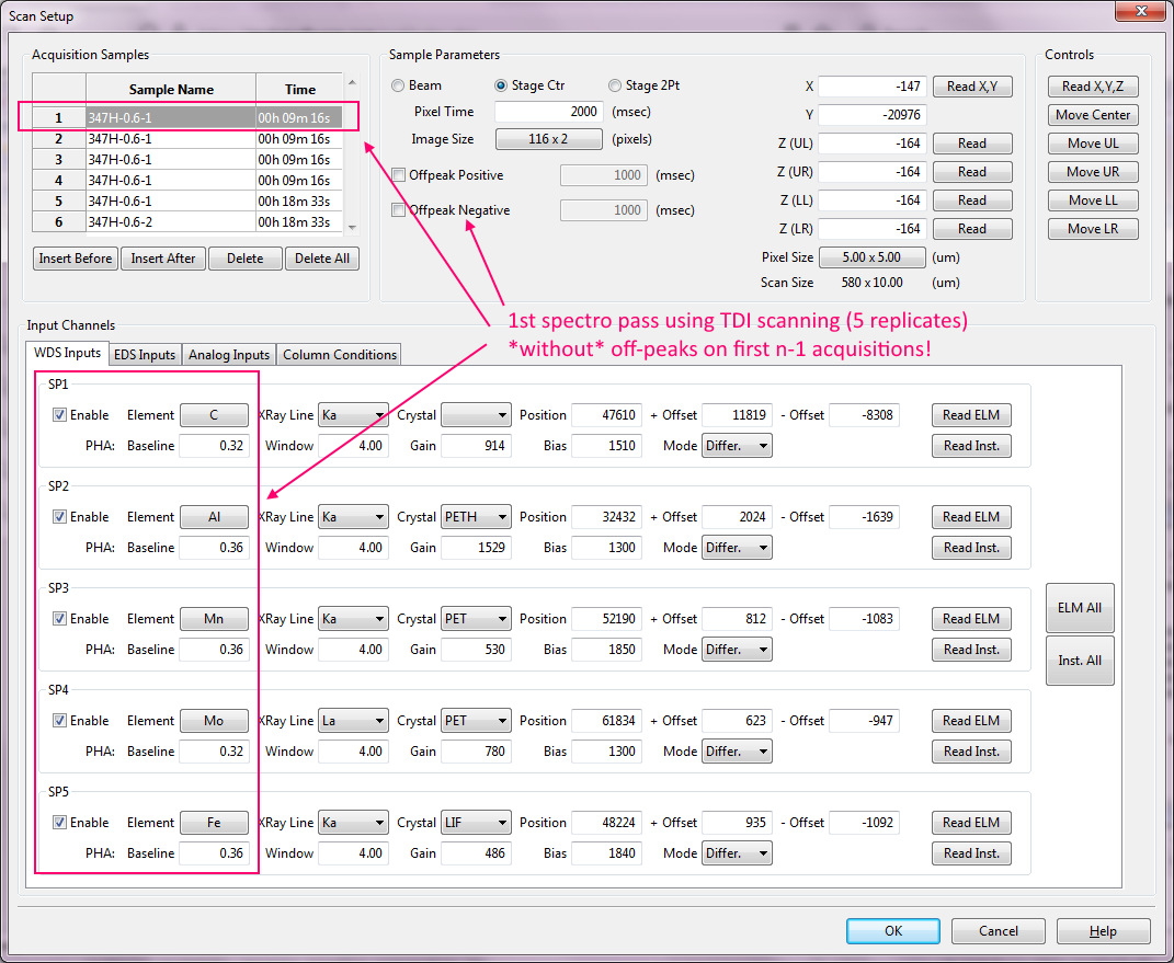
For MAN background corrected map acquisitions this is not an issue, but for off-peak background corrections we need to be aware of this.
And then, on the *final* TDI replicate map (number n), we specify the off-peak map acquisitions as seen here:
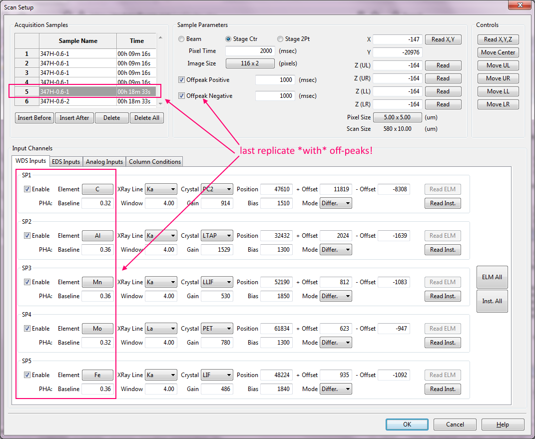
Finally, we specify an additional set(s) of map acquisitions for the next 5 elements as seen here *with* off-peak maps being acquired:

Does this make sense to everyone? It took me a while to think this all through so I expect no less from others!

Here is the followup post for quantifying these TDI scanning maps in CalcImage:
https://probesoftware.com/smf/index.php?topic=933.msg10185#msg10185

 If you are a member, please feel free to add your website URL to your forum profile